

Efficient vertical takeoff and landing aircraft
A technology for vertical take-off and landing of unmanned aerial vehicles, which is applied in the direction of aircraft, aircraft control, aircraft parts, etc., can solve the problems of local structural stress concentration and reduce the bearing efficiency of the wing structure, so as to reduce the structural weight, improve the structural bearing efficiency and Overall rigidity and strength, the effect of improving safety and reliability
- Summary
- Abstract
- Description
- Claims
- Application Information
AI Technical Summary
Problems solved by technology
Method used
Image

Examples
Embodiment 1
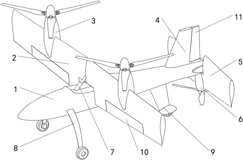
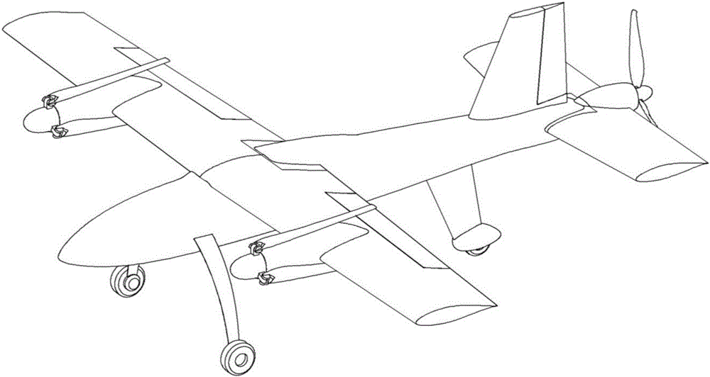
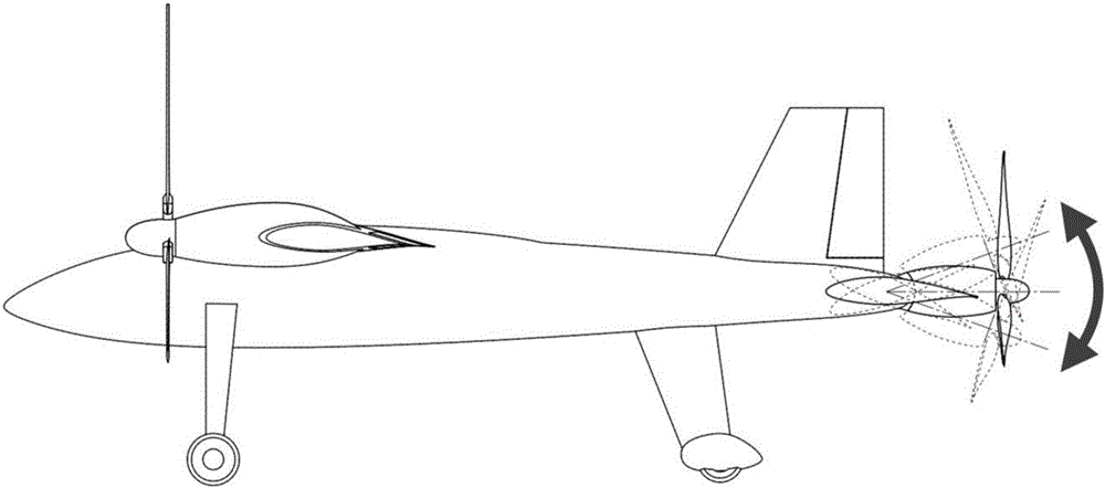
[0041] Figure 1~3 Shown is the basic structural layout and operation mode of a novel vertical take-off and landing aircraft of the present invention. The aircraft comprises a fuselage 1, a wing 2 on the top of the fuselage 1, a propeller power unit 3 on both sides of the wing 2, an aileron control surface 10, a vertical tail 4 on the upper rear side of the fuselage, and a vertical tail control surface 11. , the tiltable full-motion horizontal stabilizer 5 at the rear of the fuselage 1 and the propeller power unit 6 installed on the horizontal stabilizer, the fuselage 1 further includes a tilting actuating mechanism 7 for controlling wing deflection and a rotator that can be used for taxiing take-off and landing Front landing gear 8 and rear landing gear 9.
[0042] The propeller power unit 3 and the wing 2 are relatively fixed, and they are deflected together by the tilting mechanism 7 during the flight mode conversion process. The wing power unit 3 uses a low-speed rotor pr...
Embodiment 3
[0049] Based on the technical solution of the present invention, the inventor has carried out a lot of creative work from the initial scheme design of the aircraft to the later verification test flight. The flight efficiency under different flight conditions has a significant impact. In order to further clarify this difference, the inventor used the aircraft of the technical solution of the present invention to carry out test flights in the two states of vertical take-off and landing and fixed-wing cruise with different propellers under the same flight conditions, and tested the aircraft in each case. The minimum throttle of the power unit required at steady state was recorded, and the recorded results are shown in the table below:
[0050]
[0051] It can be seen from the above table that the aircraft using all low-speed lift propellers and high-speed propulsion propellers can maintain a relatively low throttle opening in the vertical take-off and landing phase and fixed-w...
PUM
 Abstract
Description
Claims
Application Information