Automatic locating structure for textile machine

An automatic positioning and textile machinery technology, applied in textiles and papermaking, needle punching machines, non-woven fabrics, etc., can solve the problems of complex braking mechanism, short braking delay time, large parking error, etc., and achieve the goal of braking mechanism Simple, high braking precision, small rotational inertia effect

Inactive Publication Date: 2017-05-17
杨配媛
View PDF1 Cites 2 Cited by
  • Summary
  • Abstract
  • Description
  • Claims
  • Application Information

AI Technical Summary

Problems solved by technology

When parking, especially during normal parking, due to the inertia of the equipment, the parking position of the needle loom is uncertain, which often causes the needles to still stay in the nonwoven fabric after parking, which is not conducive to cleaning and various tasks after parking. A debugging work, sometimes improper operation will cause a large number of puncture needles to break, causing certain losses and affecting production
Chinese patent CN200810123338.0 discloses a synchronous brake device for high-speed needle looms. The device starts the parking device when the spindle speed of the needle loom is 200-300 revolutions per minute. This device requires specific brake shoes to clamp and brake. Disk, starting and stopping at such a high speed, for acupuncture machines, there are defects such as complex braking mechanism, short braking delay time, and high requirements for mechanical braking equipment, and if you choose 200-300 rpm Start and stop, there are risks such as large parking errors, which cannot fully meet the design requirements

Method used


Image

  • Automatic locating structure for textile machine
  • Automatic locating structure for textile machine

Examples


Embodiment Construction

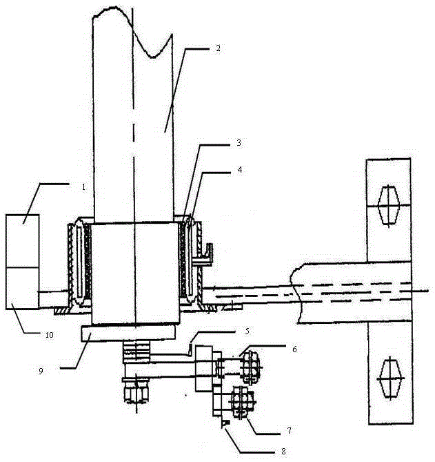
[0019] refer to figure 1 As shown, when the main motor drives the main shaft (2) to slowly decelerate under the control of the frequency converter (10), the controller (1) starts the sensing detection task, and the bottom dead center sensor (5) starts to detect the connecting rod crank (9 ) to the bottom dead center, when it is detected that the number of times the connecting rod crank (9) reaches the bottom dead center is less than 30 times per minute, the controller (1) sends a clutch clutch signal to the gear difference transmission (6), and this , the positioning gear (7) and the tooth difference transmission device (6) mesh, and the positioning gear starts to work; in the design of the tooth difference transmission device (6), the positioning gear (7) rotates 12 times every time the main shaft (2) rotates once ;When the positioning gear (7) starts and the bottom dead center sensor (5) detects that the connecting rod crank (9) reaches the bottom dead center, the counting s...


PUM


Abstract

The invention relates to an automatic locating structure for a textile machine. When a main motor drives a spindle to slowly slow down under control of a frequency converter, a bottom dead center sensor starts to detect the frequency that a crank reaches a bottom dead center; when it is detected that the frequency that the crank reaches the bottom dead center is below 30 times per minute, a locating gear controlled by a clutch is started under control of a controller, and the locating gear starts to work; meanwhile, when the bottom dead center sensor detects that the crank reaches the bottom dead center, a counting sensor starts to record the number of turns of rotation of the locating gear, when the number of turns of rotation of the locating gear reaches a certain value, the controller starts a shutdown signal, the frequency converter of the main motor stops, the crank exactly stops at a top dead center at this moment, and the function of automatic locating is achieved.

Description

technical field [0001] The invention belongs to the technical field of nonwoven machinery, and in particular relates to an automatic positioning structure for textile machinery. Background technique [0002] Acupuncture machine is an important equipment in the production of non-woven fabrics. Its working principle is roughly that the main shaft drives the crank to rotate, so that the connecting rod reciprocates. When rotating, through the power transmission of the connecting rod, it drives the needle to puncture up and down on the fiber, so that the fibers are interlaced and coiled to form a nonwoven fabric with certain strength. When parking, especially during normal parking, due to the inertia of the equipment, the parking position of the needle loom is uncertain, which often causes the needles to still stay in the nonwoven fabric after parking, which is not conducive to cleaning and various tasks after parking. In this debugging work, sometimes improper operation will ca...

Claims


Application Information

Patent Timeline
Patent Type & Authority Applications(China)
IPC IPC(8): D04H18/02
Inventor 杨配媛
Owner 杨配媛
Why Eureka
Try Eureka