Shear wall structure with rectangular steel pipe rows with vertical gaps

A technology for rectangular steel pipes and shear walls, which is applied in the direction of walls, building components, and building structures, and can solve the problem of reduced lateral bearing capacity and stiffness of steel plate shear walls, high requirements for vertical joint dimensional accuracy, and low bending and torsional stiffness and other problems, to achieve the effect of improving edge restraint, improving lateral bearing capacity, and increasing plastic bending moment value

Active Publication Date: 2022-05-24
ZHEJIANG UNIV
View PDF0 Cites 0 Cited by
  • Summary
  • Abstract
  • Description
  • Claims
  • Application Information

AI Technical Summary

Problems solved by technology

However, the steel plate shear wall widely used at present is relatively thin, and it is prone to out-of-plane instability under the action of lateral load, which brings certain problems to the performance of the steel plate shear wall: the hysteresis curve has pinch phenomenon, The energy dissipation capacity is not ideal; it needs to rely on the tension field formed after the buckling of the thin steel plate to resist the horizontal force, which requires the surrounding frame beams and columns to be strong enough to meet the conditions for the formation of the tension field
However, shear walls with vertical joints also have great limitations: (1) Due to the opening of vertical joints, the lateral load-bearing capacity and stiffness of steel plate shear walls are greatly reduced, which is harmful to the structure under wind load and frequent earthquakes. (2) Since the cross-section of the columbine between seams is a long and narrow section with free edges on both sides, the width-to-thickness ratio limit to ensure its local stability is strict, so it is often required in practice Relatively thick steel plates are used; (3) Since the cross-section of the small column between the seams is a narrow and long strip, the bending and torsional rigidity outside the plane is small, and it is prone to bending and torsional instability under load; (4) The dimensional accuracy of the vertical seam High requirements, often require high-precision processing methods such as laser cutting, making production difficult

Method used


Image

  • Shear wall structure with rectangular steel pipe rows with vertical gaps
  • Shear wall structure with rectangular steel pipe rows with vertical gaps
  • Shear wall structure with rectangular steel pipe rows with vertical gaps

Examples


Embodiment 1

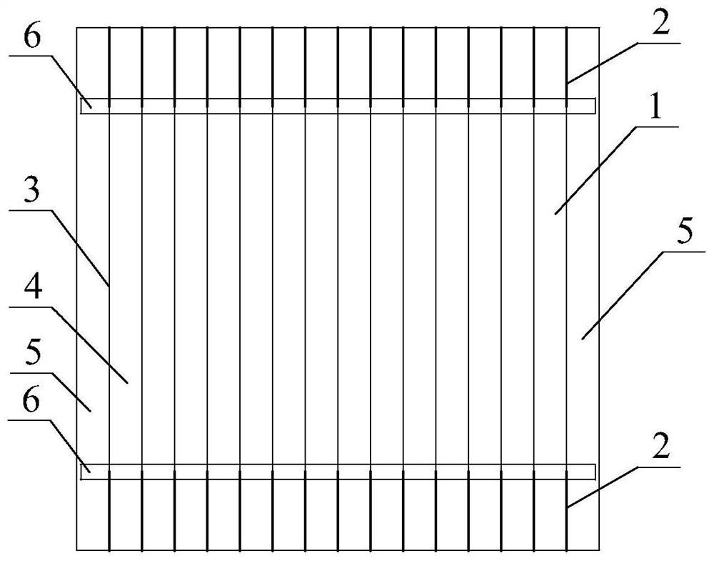
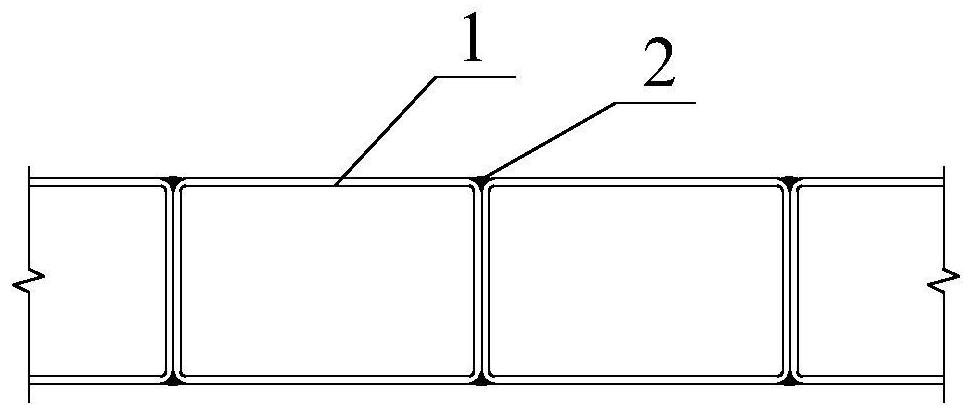
[0043] like figure 1 As shown, the ends of the adjacent rectangular steel pipes 1 are connected by connecting welds 2 between the ends of the upper and lower ends, and the two adjacent steel pipes are connected by the connecting welds at the junction of the steel pipe flange and the web, as shown in the figure. figure 2 As shown, a row of bending small columns 4 located in the middle of the rectangular steel pipe 1 is formed, thereby forming two upper and lower rows of connection welds 2 and a row of vertical gaps 3 between the upper and lower rows of connection welds 2, adjacent vertical The gap is separated by a rectangular steel pipe, and each bending column 4 is composed of a single rectangular steel pipe 1 .

[0044] And weld a transverse reinforcing steel strip 6 at both ends of the middle row of bending small columns 4 to strengthen, that is, the junction of the upper row of connection welds 2 and the vertical gap 3 and the lower row of connection welds 2 and the verti...

Embodiment 2

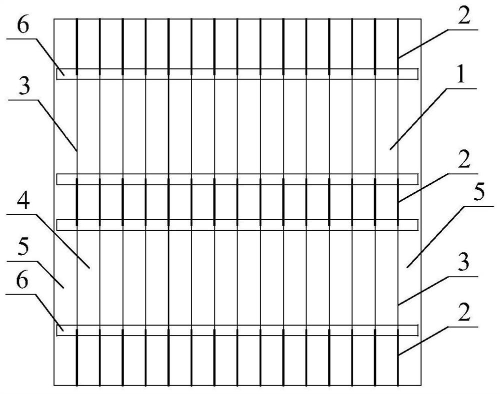
[0047] like image 3 As shown, the adjacent rectangular steel pipes 1 are connected by connecting welds 2 between the upper ends, the middle parts and the lower ends, forming two rows of bending columns 4 located in the middle of the rectangular steel pipes 1, forming three upper, middle and lower parts. Row of connection welds 2 and vertical gaps 3 between the upper and middle row of connection welds 2 and between the middle and lower row of connection welds 2; A transverse reinforcing steel strip 6 is welded for reinforcement, that is, at the junction of the upper row of connection welds 2 and the upper row of vertical gaps 3, the junction of the middle row of connection welds 2 and the upper row of vertical gaps 3, and the middle row of connection welds. Horizontal reinforcement steel strips 6 arranged horizontally and horizontally are welded at the junction of seam 2 and the lower row of vertical gaps 3 and at the junction of the lower row of connection welds 2 and the low...

Embodiment 3

[0050] like Figure 4 As shown, take two adjacent rectangular steel pipes 1 as a group, each group of rectangular steel pipes 1 is connected by the entire vertical connecting weld 2, and adjacent two groups of rectangular steel pipes 1 are between the ends of the upper and lower ends. They are all connected by connecting welds 2 to form a row of bending small columns 4 located in the middle of the rectangular steel pipe 1, and each bending small column 4 is composed of two rectangular steel pipes 1, thereby forming two upper and lower rows of connecting welds 2 and the upper and lower columns. Alternately arranged connection welds 2 and vertical gaps 3 between the two rows of connection welds 2; and weld a transverse reinforcement steel strip 6 at both ends of each group of bending columns 4 in the middle to strengthen, and the transverse reinforcement steel strips The four sides of 6 are welded with the rectangular steel pipe 1 by fillet welds.

[0051] The specific elevatio...


PUM


Abstract

The invention discloses a rectangular steel pipe row shear wall structure with vertical gaps. It is mainly composed of a plurality of vertically arranged rectangular steel pipes closely arranged horizontally and horizontally. The adjacent rectangular steel pipes are connected by connecting welds arranged at intervals, and the connecting welds at the junction of the steel pipe flange and the web Two adjacent steel pipes are connected. The vertical discontinuity of the connection weld forms a vertical gap between the rectangular steel pipes, and the rectangular steel pipes between the parallel vertical gaps form a small bending column, which bends and deforms under the action of the lateral load, so that the shear wall is under load. The plastic hinge formation at the end of the lower flexural column occurs before the overall instability of the shear wall, the out-of-plane instability of the flexural column and the local instability of the steel pipe wall. The invention has the characteristics of large anti-lateral bearing capacity, large out-of-plane rigidity, large anti-lateral rigidity, good seismic performance, good ductility, full energy consumption hysteresis loop and the like.

Description

technical field [0001] The invention relates to the technical field of building structure engineering, in particular to a rectangular steel tube row shear wall structure with vertical slits. Background technique [0002] Steel plate shear wall is a new type of lateral force resistance structure of steel structure buildings. Compared with traditional steel support and concrete shear wall or core tube structure, this structure has the concept of good ductility and easy realization of multiple seismic defense lines of the structure. , It has the advantages of convenient production and construction, and can increase the usable area of ​​the building. However, the currently widely used steel plate shear wall is relatively thin, which is prone to out-of-plane instability under the action of lateral load, which brings certain problems to the performance of the steel plate shear wall: the hysteresis curve has a pinch phenomenon, The energy dissipation capacity is not ideal; it need...

Claims


Application Information

Patent Timeline
Patent Type & Authority Patents(China)
IPC IPC(8): E04B2/58
CPCE04B2/58
Inventor 张磊童根树
Owner ZHEJIANG UNIV
Why Eureka
Try Eureka