Vertical shaft restoration and reinforcement structure and restoration and reinforcement construction method

A technology for strengthening structures and construction methods, applied in basic structure engineering, shaft equipment, excavation, etc., can solve problems such as shaft scrapping, expansion of collapse range, exposed original rock, etc., and achieve the effect of short construction period, easy construction and simple structure

Active Publication Date: 2017-05-17
WUHAN SURVEYING GEOTECHN RES INST OF MCC
View PDF6 Cites 24 Cited by
  • Summary
  • Abstract
  • Description
  • Claims
  • Application Information

AI Technical Summary

Problems solved by technology

[0002] At present, most mines in China use the mine transportation method of shaft + adit. As the service life of the shaft increases, the lining of the shaft wall is gradually worn and damaged, resulting in the exposure of the original rock; under the impact load of mine feeding, the shaft wall will be Collapse occurs; factors such as poor quality of the rock mass on the shaft wall and water seepage can easily cause the scope of the collapse to expand. If the situation is serious, it will easily cause problems such as well blocking and shaft scrapping; seriously affect the operation of the production line
At present, there are few repair and reinforcement technologies for shaft collapse. Generally, after shaft collapse and other problems occur, the site is usually re-selected to build the shaft, and the mine equipment is relocated or updated, causing great economic losses.

Method used


Image

  • Vertical shaft restoration and reinforcement structure and restoration and reinforcement construction method
  • Vertical shaft restoration and reinforcement structure and restoration and reinforcement construction method
  • Vertical shaft restoration and reinforcement structure and restoration and reinforcement construction method

Examples


Embodiment

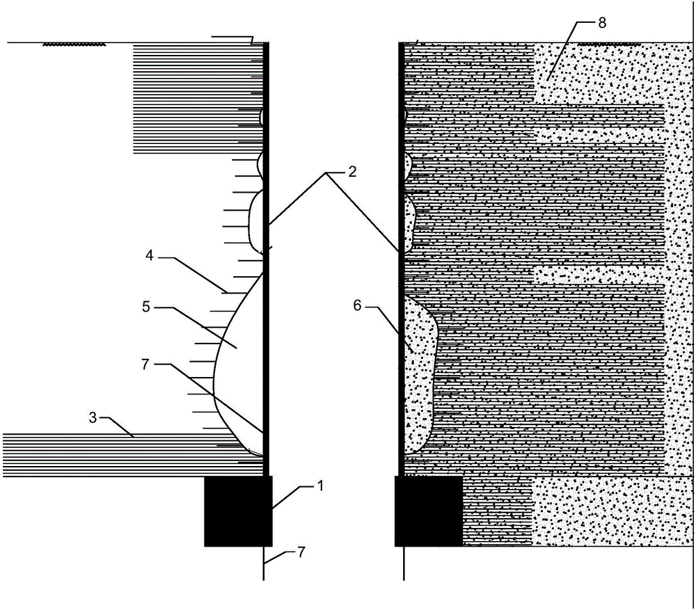
[0025] Embodiment: This embodiment is specifically aimed at the repair and reinforcement construction of a mineral shaft in a cement plant in Yunnan. The shaft adopts short bolt grouting measures in the early stage, and the water seepage rate is reduced by 20-35%, and the shaft wall still collapses, which is not enough to meet the production demand. In order to solve the problems of shaft wall collapse and water seepage, the technical scheme of the present invention is adopted to reinforce and repair the shaft wall. The specific implementation steps are as follows:

[0026] (1) First, according to the seepage situation of the shaft and the design drawings, bolt drilling and grouting are used at the seepage part of the shaft wall to reinforce the surrounding rock in the broken and seepage area inside the shaft, and to stop the seepage part of the shaft wall; among them, the wellbore The shaft wall of 0~-110m is better. There are 4 bolts in one ring, each hole is 3m deep, and the ri...


PUM


Abstract

The invention provides a vertical shaft restoration and reinforcement structure and a restoration and reinforcement construction method. The vertical shaft restoration and reinforcement construction method comprises the steps that firstly, surrounding rock in a fractured and water-seepage area inside a vertical shaft is reinforced through anchor rod drilling grouting, and water stopping is conducted on to-be-restored parts; secondly, a plurality of drainage holes are drilled in water-seepage parts, water in the water-seepage parts is introduced into a soil layer under the bottom of the vertical shaft through a drainage system, an annular foundation is constructed on shaft wall surrounding rock meeting the third-level rock mass standard or a complete shaft wall under the to-be-restored parts of the vertical shaft, and a steel plate drum is mounted on the annular foundation; and thirdly, concrete is poured between the steel plate drum and the shaft wall in a filled mode through a vertical concrete conveying pipe to fix the steel plate drum to the inner wall of the vertical shaft. The vertical shaft restoration and reinforcement structure is simple, short in construction period, small in influence on a production line, convenient to construct, replace and repair and suitable for the conditions of vertical shaft blocking and shaft wall collapse.

Description

Technical field [0001] The invention belongs to the cross field of geotechnical engineering and mining engineering, and specifically relates to a novel shaft repair and reinforcement structure and a repair and reinforcement construction method which can well solve the problems of water seepage, collapse and blockage of the shaft wall. Background technique [0002] At present, most domestic mines adopt the mine transportation method of shaft + flat tunnel. As the service life of the shaft increases, the shaft wall lining of the shaft is gradually worn and damaged, causing the original rock to be exposed; under the impact of the impact load of the mine, the shaft wall will become Collapse occurs; in the area of ​​poor shaft wall rock mass, water seepage and other factors are likely to cause the collapse of the area to expand, the situation is serious, it is easy to cause problems such as well blockage, shaft scrapping, etc.; seriously affecting the operation of the production line. ...

Claims


Application Information

Patent Timeline
Patent Type & Authority Applications(China)
IPC IPC(8): E21D5/04E02D17/08
CPCE02D17/08E21D5/04
Inventor 颜克诚占仲国魏帮明赵伟伟陈哲俊邓学灯王勇衡冀阳桂智勇詹建华
Owner WUHAN SURVEYING GEOTECHN RES INST OF MCC
Why Eureka
Try Eureka