Internal combustion engine structure with superheated water being sprayed into cylinder

An in-cylinder injection, internal combustion engine technology, applied to internal combustion piston engines, combustion engines, mechanical equipment, etc., can solve the problems of wasting energy consumption, exhaust heat loss in the cylinder, limiting the improvement of the thermal efficiency of the internal combustion engine, etc. Longevity and effect of reducing heat loss

Active Publication Date: 2017-05-17
TONGJI UNIV
View PDF5 Cites 19 Cited by
  • Summary
  • Abstract
  • Description
  • Claims
  • Application Information

AI Technical Summary

Problems solved by technology

[0004] At the same time, the exhaust gas discharged from the cylinder takes away about one-third of the heat in the cylinder. At present, injecting cold water into the cylinder can reduce the end-of-compression temperature in the cylinder and avoid knocking a...

Method used


Image

  • Internal combustion engine structure with superheated water being sprayed into cylinder
  • Internal combustion engine structure with superheated water being sprayed into cylinder
  • Internal combustion engine structure with superheated water being sprayed into cylinder

Examples


Embodiment 1

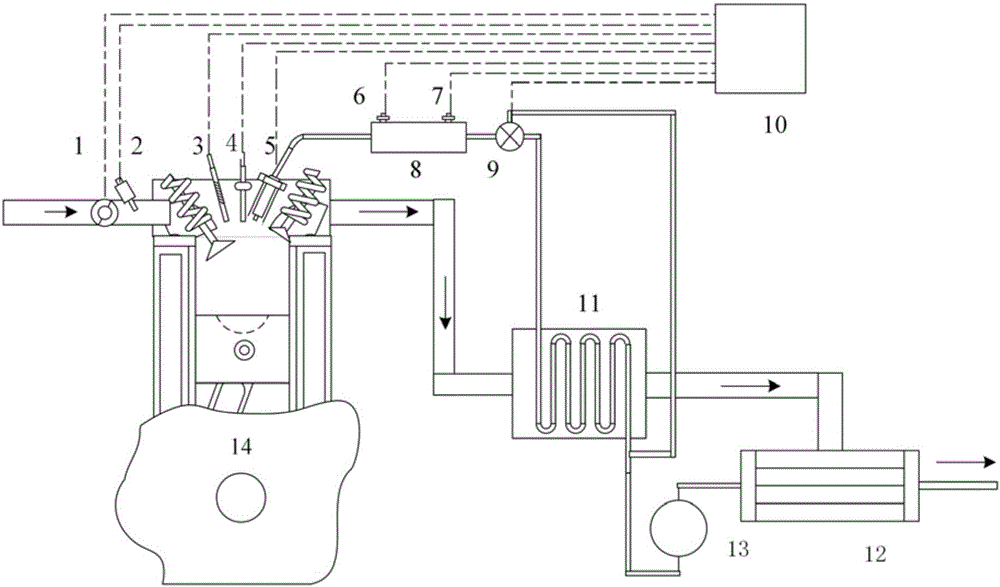
[0020] refer to figure 1 , an internal combustion engine structure for injecting superheated water in the cylinder, including a throttle valve 1, a fuel injector 2, a pressure sensor 3, a spark plug 4, a water spray nozzle 5, a thermocouple 6, a rail pressure sensor 7, a high-pressure water rail 8, and three Through solenoid valve 9, electronic control unit 10, heat exchanger 11, condenser 12, high-pressure water pump 13, internal combustion engine cylinder block 14, condenser 12 is connected to the exhaust output end of the internal combustion engine cylinder block, and the output end of condenser 12 is connected to the heat exchange The input end of the device 11 and the first input end of the three-way electromagnetic valve 9, the output end of the heat exchanger 11 is connected to the second input end of the three-way electromagnetic valve 9, and the output end of the three-way electromagnetic valve 9 is connected to the high-pressure water rail 8, The high-pressure water ...


PUM


Abstract

The invention relates to an internal combustion engine structure with superheated water being sprayed into a cylinder. The internal combustion engine structure with the superheated water being sprayed into the cylinder comprises an internal combustion engine cylinder block, a throttle valve, an oil sprayer, a sparking plug and a water spraying nozzle and further comprises a condenser, a heat exchanger, a three-way electromagnetic valve, a high-pressure water rail and an electronic control unit. The condenser is connected to the exhaust output end of the internal combustion engine cylinder block. The output end of the condenser is connected with the heat exchanger and a first input end of the three-way electromagnetic valve. The output end of the heat exchanger is connected with a second input end of the three-way electromagnetic valve. The output end of the three-way electromagnetic valve is connected with the high-pressure water rail. The high-pressure water rail is connected with the water spraying nozzle. According to the internal combustion engine structure with the superheated water being sprayed into the cylinder, the high-pressure superheated water is sprayed into the cylinder, high-temperature steam is formed through flashing boiling of the superheated water, heat in the cylinder is further absorbed, the superheated water is used as an extra work doing medium, and the heat efficiency of an internal combustion engine system is improved; a control model is established to achieve real-time calculation of the pressure and temperature inside the cylinder, so that it can be guaranteed that the water sprayed into the cylinder is in the superheated state, and therefore the heat efficiency of the internal combustion engine is improved.

Description

technical field [0001] The invention belongs to the technical field of internal combustion engines, in particular to an internal combustion engine structure for injecting superheated water in a cylinder. Background technique [0002] The energy consumption of motor vehicles has received widespread attention, and the emission standards for carbon dioxide and fuel consumption have become increasingly stringent. In order to further improve the working efficiency of motor vehicles and reduce energy consumption, the internal combustion engine supercharging and miniaturization technology is currently proposed. After using a higher intake pressure, the cylinder volume can be reduced without losing power and torque output, thereby reducing With this advantage, the small-displacement supercharged internal combustion engine is showing a tendency to replace the naturally aspirated internal combustion engine as the mainstream power source of motor vehicles. [0003] However, the therma...

Claims


Application Information

Patent Timeline
IPC IPC(8): F02M25/03F01N5/02F02B47/02
CPCF01N5/02F02B47/02F02M25/03Y02T10/12
Inventor 吴志军康哲张哲豪邓俊胡宗杰李理光
Owner TONGJI UNIV
Why Eureka
Try Eureka