
Heat exchanging chamber and coke oven

A heat exchange chamber and coke oven technology, applied in the coking field, can solve the problems of complex coke oven structure, excessive nitrogen oxides, and high air temperature, and achieve the effects of simplifying the process and coke oven system, reducing emissions, and reducing combustion temperature

Inactive Publication Date: 2017-05-17
HUATAI YONGCHUANG BEIJING TECH CO LTD
View PDF4 Cites 3 Cited by
  • Summary
  • Abstract
  • Description
  • Claims
  • Application Information

AI Technical Summary

Problems solved by technology

[0004] The inventors found that there are at least the following problems in the prior art: traditional coke ovens use regenerators to utilize the heat of exhaust gas, which requires regenerator checker bricks and gas reversing, which makes the structure of coke ovens complicated and is preheated by regenerators. After the air temperature is higher, so the nitrogen oxides generated when it burns with coal gas exceed the standard

Method used


Image

  • Heat exchanging chamber and coke oven
  • Heat exchanging chamber and coke oven

Examples


Embodiment 1

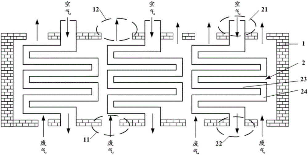
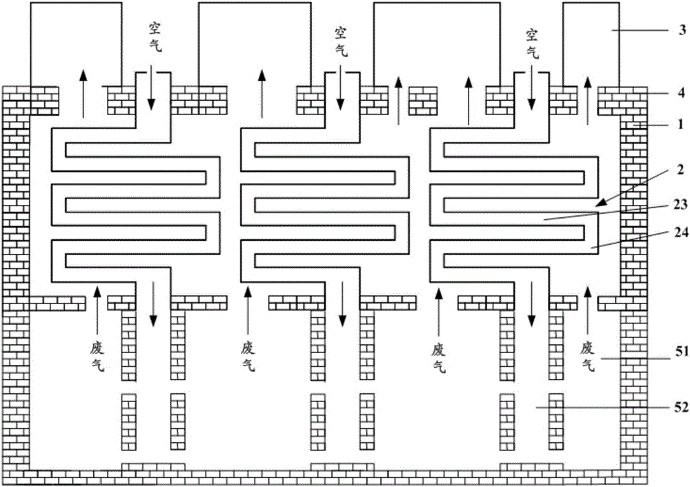
[0025] like figure 1 and 2 As shown, this embodiment provides a heat exchange chamber for a coke oven, which includes a chamber body 1 and a heat exchange tube 2 . The heat exchange tube 2 is arranged in the chamber body 1; the chamber body 1 is provided with an exhaust gas inlet 11 and an exhaust gas outlet 12; the two ends of the heat exchange tube 2 are an air inlet 21 and an air outlet 22 respectively.

[0026] Specifically, as figure 1 As shown, the heat exchange chamber includes a chamber body 1 and a heat exchange tube 2, wherein the chamber body 1 refers to the main chamber of the heat exchange tube 2, which is provided with an exhaust gas inlet 11 and an exhaust gas outlet 12; the heat exchange tube 2 is arranged in In the chamber body 1, its two ends are respectively an air inlet 21 and an air outlet 22. Wherein, the air inlet 21 and the air outlet 22 are located on the wall of the chamber body 1 or outside the chamber body 1). However, there is a gap between the...

Embodiment 2

[0045] like figure 1 and 2 As shown, this embodiment provides a coke oven, including the heat exchange chamber provided in Embodiment 1.

[0046] The coke oven in this embodiment utilizes the waste heat of the exhaust gas through the heat exchange chamber. For a detailed description of the structure of the heat exchange chamber, see Embodiment 1, which will not be repeated here.

[0047]The difference from the traditional coke oven is that the traditional coke oven utilizes the waste heat of the coke oven exhaust gas through the regenerator, while the coke oven of this embodiment utilizes the waste heat of the exhaust gas by setting up a heat exchange chamber, and the waste gas is preheated. During heat utilization, there is no need for heat storage lattice bricks, reducing the reversing device, simplifying the waste heat utilization process and coke oven system. At the same time, the air temperature preheated by the coke oven in this embodiment is lower than the air tempera...


PUM


Abstract

The invention provides a heat exchanging chamber and a coke oven and belongs to the technical field of coking. The heat exchanging chamber and the coke oven can solve the problems that an existing coke oven exhaust gas waste heat utilization process is complex, and nitrogen oxide emission exceeds standard. The heat exchanging chamber comprises a chamber body and a heat exchanging pipe arranged in the chamber body. The chamber body is provided with an exhaust gas inlet and an exhaust gas outlet. The two ends of the heat exchanging pipe are an air inlet and an air outlet. The heat exchanging chamber can be used for exhaust gas waste heat utilization of the coke oven, and the exhaust gas waste heat utilization process and a coke oven system are simplified. Meanwhile, the burning temperature of air and coal gas in a burning chamber of the coke oven can be reduced, and nitrogen oxide emission can be effectively reduced.

Description

technical field [0001] The invention belongs to the technical field of coking, and particularly relates to a heat exchange chamber and a coke oven. Background technique [0002] In the coking industry, when coking in a coke oven, the heat generated by the combustion of gas and air is usually used to heat the carbonization chamber to realize the carbonization of coal, and the waste gas generated by the combustion of gas and air can be used to preheat the air to be burned. [0003] The traditional coke oven uses a regenerator to preheat the air. For example, in a single-heat coke oven, the air is preheated through the regenerator, and then passes through the chute to the bottom of the vertical fire (in the combustion chamber), and the coke oven gas passes through the gas. The tube bricks are sent to the bottom of the vertical fire channel, where the gas and air are mixed and burned at the bottom of the vertical fire channel. The regenerator is located below the combustion cha...

Claims


Application Information

Patent Timeline
Patent Type & Authority Applications(China)
IPC IPC(8): F28D7/08C10B17/00
CPCY02P20/129F28D7/082C10B17/00
Inventor 徐列姚梈赵楠楠姜士敏王浩强
Owner HUATAI YONGCHUANG BEIJING TECH CO LTD
Learn More