
Distributed energy source system used for solar unmanned aerial vehicle

A solar unmanned aerial vehicle, distributed energy technology, applied in photovoltaic power generation, photovoltaic modules, electrical components, etc., can solve problems such as low system energy utilization, solar cell array clamping, solar cell array operating point drift, etc.

Inactive Publication Date: 2017-05-17
CHINA ELECTRONIC TECH GRP CORP NO 18 RES INST
View PDF6 Cites 10 Cited by
  • Summary
  • Abstract
  • Description
  • Claims
  • Application Information

AI Technical Summary

Problems solved by technology

During the take-off, cruising, and landing phases of the UAV, the incident angle and temperature of the sun will change greatly, which will easily cause the working point of the solar cell array to drift. In addition, the voltage of the battery is low during the charging stage, which will clamp the solar cell array. , in order to make better use of the energy emitted by the solar array, it is necessary to adopt an appropriate way to manage the energy system
[0003] At present, the existing technology retrieved is the simple construction of the solar UAV energy management system, which only realizes the simple scheduling of solar cells and lithium batteries, and does not consider the flight trajectory, wing airfoil curvature, and working conditions during the actual flight. The influence of factors such as temperature and wingspan on the power utilization of the energy system, the energy utilization of the system is low

Method used


Image

  • Distributed energy source system used for solar unmanned aerial vehicle

Examples


Embodiment Construction

[0016] In order to further understand the invention content, characteristics and effects of the present invention, the following examples are given, and detailed descriptions are as follows in conjunction with the accompanying drawings:

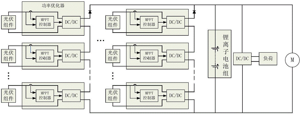
[0017] see figure 1 , a distributed energy system for solar drones, comprising:

[0018] multiple photovoltaic modules;

[0019] A power optimizer electrically connected to each photovoltaic module;

[0020] One 80V-120V high-voltage busbar and one 27V-29V low-voltage busbar; among them:

[0021] Each power optimizer includes an MPPT controller and a DC-DC converter; the output terminal of each photovoltaic module is electrically connected to the input terminal of a DC-DC converter; the connection between the photovoltaic module and the DC-DC converter The transmission wire is connected to the MPPT controller; multiple DC-DC converters are connected in series with the 80V~120V high-voltage bus, and multiple DC-DC converters are connected i...


PUM


Abstract

The invention discloses a distributed energy source system used for a solar unmanned aerial vehicle. The system is characterized by at least comprising a plurality of photovoltaic modules, a power optimizer electrically connected to each photovoltaic module, a high-voltage bus of 80V-120V and a low-voltage bus of 27V-29V, wherein each power optimizer comprises an MPPT controller and a DC-DC converter; an output terminal of each photovoltaic module is electrically connected to an input terminal of one DC-DC converter; a transmission conductor between the photovoltaic module and the DC-DC converter module is connected to the MPPT controller; after connected in series in sequence, the DC-DC converters are connected to the high-voltage bus of 80V-120V; after connected in series in sequence, the DC-DC converters are connected to a lithium ion battery series; and after connected in series in sequence, the DC-DC converters are connected to the low-voltage bus through one DC-DC converter. According to the system, the conversion efficiency of the photovoltaic modules can be improved.

Description

technical field [0001] The invention relates to the technical field of power supply control for space vehicles, in particular to a distributed energy system for solar-powered drones. Background technique [0002] The solar-powered unmanned aircraft has long cruising time, high flying altitude, wide coverage area, and can perform a variety of tasks, which has irreplaceable advantages of conventional aircraft. The solar unmanned aircraft energy system uses photovoltaic conversion to convert solar radiation energy into electrical energy, providing long-term power energy for unmanned aerial vehicles. The power generation of the solar cell array is very uneven within a day, and a suitable power control method is very necessary. During the take-off, cruising, and landing phases of the UAV, the incident angle and temperature of the sun will change greatly, which will easily cause the working point of the solar cell array to drift. In addition, the voltage of the battery is low dur...

Claims


Application Information

Patent Timeline
IPC IPC(8): H02S40/30
CPCH02S40/30Y02E10/50
Inventor 李钏付增英呼文韬邓绍刚周君于智航王寅韩献堂赵超张丹红刘敏娟王春梅
Owner CHINA ELECTRONIC TECH GRP CORP NO 18 RES INST
Learn More