Combined dust removal equipment

A dust removal equipment and combined technology, which is applied in the field of combined dust removal equipment, can solve the problems of difficulty in making dust removal equipment, single structure of dust removal equipment, and limited use range, and achieve the effects of low production cost, reduced transportation cost, and reasonable structure

Pending Publication Date: 2017-05-24
苏州格劳兰净化设备有限公司
View PDF3 Cites 4 Cited by
  • Summary
  • Abstract
  • Description
  • Claims
  • Application Information

AI Technical Summary

Problems solved by technology

Existing dust removal equipment manufacturers still have certain problems in the production of dust removal equipment. For example, the existing dust removal equipment generally includes a box body and a filter cartridge installed in the box body. The filter cartridge is pulled and installed in the box for easy replacement. The structure of the dust removal equipment of this structure is relatively simple, and can only be customized according to the dust removal amount required by the customer. The scope of use is very limited, so that when customers have different needs, Since different types of dust removal equipment require different molds during production, this difference increases the production cost. At the same time, the production of the dust removal equipment is also difficult and requires a lot of welding operations

Method used


Image

  • Combined dust removal equipment
  • Combined dust removal equipment
  • Combined dust removal equipment

Examples


Embodiment Construction

[0028] The present invention will be described in further detail below through specific examples.

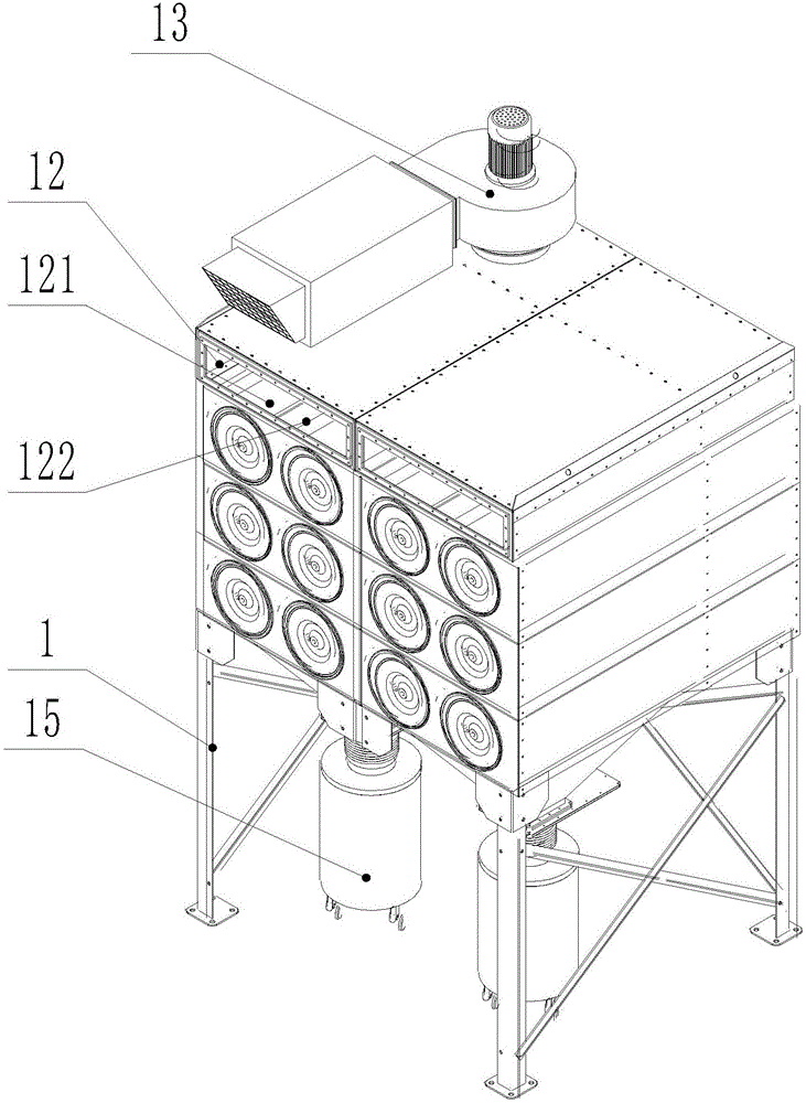
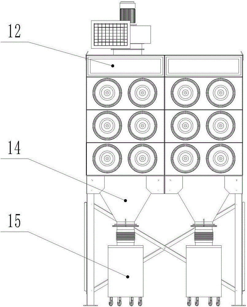
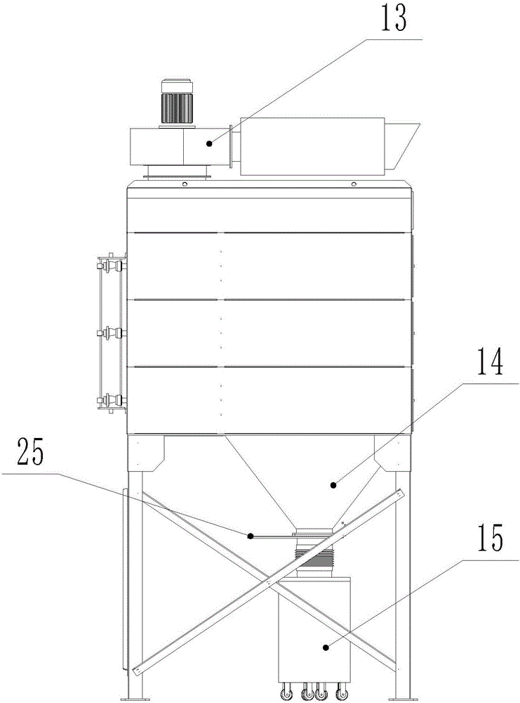
[0029] Such as Figures 1 to 6 As shown, the definitions of up, down, front, back, left and right are as follows figure 2 The state shown in is the baseline, and the observer faces figure 2 Determined, the vertical paper faces inwards.

[0030] A combined dust removal device, comprising at least one dust remover unit, the dust remover unit includes several dust removal module monomers 2, the dust removal module monomers 2 are stacked and installed up and down, and each dust removal module monomer 2 is a cuboid structure , wherein, the dust removal module monomer 2 contained in each dust collector unit has the same size, and the dust removal module monomer 2 of different dust collector units can have the same height and front and rear length, and the left and right widths can be different.

[0031] Such as Figure 5 with Image 6As shown, the dust removal module monomer 2 ...


PUM


Abstract

The invention discloses combined dust removal equipment, which comprises at least one dust remover unit, wherein the dust remover unit comprises a plurality of dust removal module single bodies in vertical overlapped arrangement; each dust removal module single body comprises a front plate, a rear plate, a pattern plate, a left side plate and a right side plate; the pattern plate divides each dust removal module single body into an air inlet cavity and an air extraction cavity; a filter tube is arranged in each air inlet cavity; all of the air inlet cavities form a dust removal chamber; all of the air extraction cavities form an air purification chamber; an upper functional cavity is fixed on the dust removal module single body positioned at the uppermost side; a dust-containing gas inlet is formed in the upper functional cavity; the dust-containing gas inlet communicates with the dust removal chamber; the lower end part of the dust removal module single body positioned at the lowermost side is provided with a dust collecting hopper; the lower part of the dust collecting hopper is provided with a dust collecting device; a negative pressure air extraction fan is connected with the air purification chamber. The dust removal equipment uses a combined installation mode; high speed and convenience are realized; different requirements of customers can be met only by using one set of dust removal equipment mold by using different assembly modes; the use range is wide; the manufacturing is easy.

Description

technical field [0001] The invention relates to the field of dust removal, in particular to a combined dust removal device. Background technique [0002] Dust removal equipment is a kind of equipment that separates dust from the air flow. It is a relatively common industrial equipment in industrial production. After the pressure difference, the airflow with dust enters the dust collector and is filtered by filter components such as filter cartridges or cloth bags, and the filtered clean gas is discharged through the air outlet. On the one hand, dust removal equipment can eliminate pollution and protect the environment, on the other hand, it can greatly improve the working environment of workers, and can also recycle useful materials, which combines many advantages. Existing dust removal equipment manufacturers still have certain problems in the production of dust removal equipment. For example, the existing dust removal equipment generally includes a box body and a filter c...

Claims


Application Information

Patent Timeline
IPC IPC(8): B01D46/00B01D46/24B01D46/48
CPCB01D46/0041B01D46/0084B01D46/2411B01D46/48B01D2267/30B01D46/56B01D46/71Y02A50/2351
Inventor 徐晓东
Owner 苏州格劳兰净化设备有限公司
Why Eureka
Try Eureka