Eureka AIR delivers breakthrough ideas for toughest innovation challenges, trusted by R&D personnel around the world.

Magnetic control K-TIG welding gun based on water-cooled permanent magnets

A permanent magnet and welding torch technology, applied in welding equipment, welding rod characteristics, arc welding equipment and other directions, can solve the problems of increasing arc restraint effect and penetration ability, small process window for qualified welding seam, unfavorable and stable penetration of small holes, etc. Achieve the effect of increasing penetration ability, avoiding demagnetization, and compact structure of the welding gun

Inactive Publication Date: 2017-05-24
TIANJIN UNIV
View PDF6 Cites 5 Cited by
  • Summary
  • Abstract
  • Description
  • Claims
  • Application Information

AI Technical Summary

Problems solved by technology

[0010] What the present invention aims to solve is that when the K-TIG torch welds metal materials with low thermal conductivity, as the thermal conductivity of the material increases, the stability of the small holes decreases. The technical problem of penetrating small holes and obtaining qualified welds with a small process window is to provide a magnetically controlled K-TIG welding torch based on water-cooled permanent magnets. Permanent magnets are used instead of electromagnets to construct a circular magnetic field to compress the K-TIG welding arc, which can increase The confinement effect and penetration ability of the arc; at the same time, a water cooling device is installed to surround the permanent magnet to achieve timely cooling and reduce demagnetization, thereby improving the stability of the obtained magnetic field and better restraining and controlling the arc

Method used


Image

  • Magnetic control K-TIG welding gun based on water-cooled permanent magnets
  • Magnetic control K-TIG welding gun based on water-cooled permanent magnets
  • Magnetic control K-TIG welding gun based on water-cooled permanent magnets

Examples


Embodiment Construction

[0032] In order to further understand the content, characteristics and effects of the present invention, the following examples are given, and detailed descriptions are as follows in conjunction with the accompanying drawings:

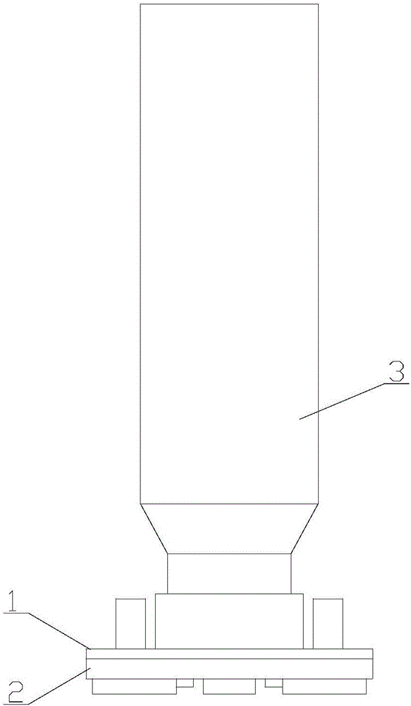
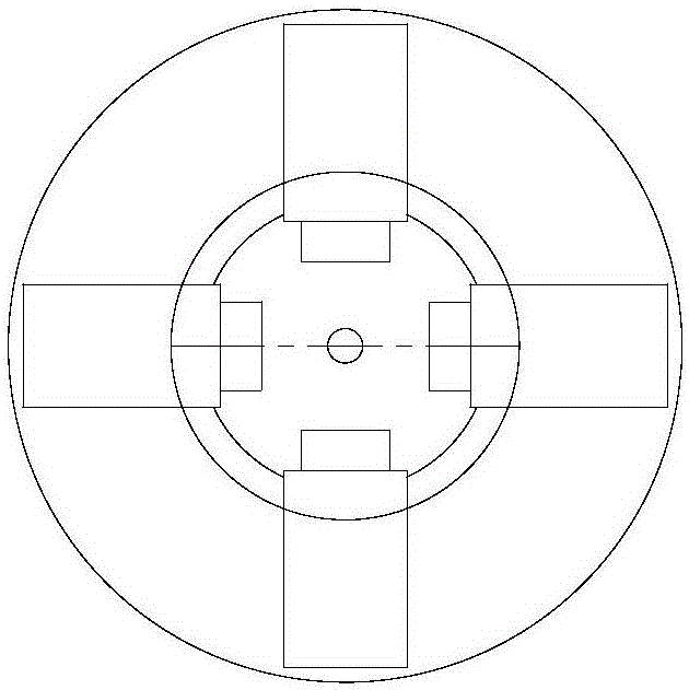
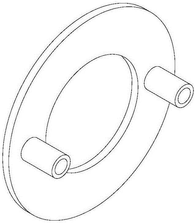
[0033] Such as figure 1 and figure 2 As shown, this embodiment provides a magnetically controlled K-TIG welding torch based on water-cooled permanent magnets, which mainly includes a cover 1 and a housing 2 connected to the lower part of the cover 1. The cover 1 and the housing 2 form a The closed space is fixed at the tip of the welding torch 1. Permanent magnets uniformly distributed in the radial direction are arranged in the closed space, and a water cooling device is arranged around the permanent magnets. In this way, the confinement effect and wear-through of the arc are increased when using multi-magnetic poles to construct a pointed magnetic field. Under the premise of improving the permeability, the purpose of cooling the permanent magnet in t...


PUM


Abstract

The invention belongs to the technical field of K-TIG welding guns and discloses a magnetic control K-TIG welding gun based on water-cooled permanent magnets. The magnetic control K-TIG welding gun mainly comprises a cover body and a holding body connected to the lower portion of the cover body. The cover body and the holding body form a closed space and are fixed to the gun head of the welding gun. The radially and evenly distributed permanent magnets are arranged in the closed space, and water cooling devices are arranged around the permanent magnets. According to the magnetic control K-TIG welding gun, the permanent magnets are used for replacing electromagnets to construct a circular magnetic field to compress K-TIG welding electric arcs, thus the restraining effect and penetrability of the electric arcs can be enhanced; and meanwhile, the water cooling devices are arranged to wrap the permanent magnets so as to achieve the purposes of in-time cooling and demagnetization reduction, thus the stability of the obtained magnetic field is improved, and the electric arcs are restrained and controlled better.

Description

technical field [0001] The invention belongs to the technical field of a K-TIG welding torch, and in particular relates to a magnetically controlled K-TIG welding torch which increases an adjustable magnetic field and shrinks an arc column. Background technique [0002] TIG welding can achieve high-quality welding, but the existing TIG welding arc energy density is low, which limits its welding efficiency. Based on the traditional TIG welding torch, a new perforation welding process method is obtained through the cathode shrinkage effect with a large welding current, which is called CF-TIG welding or K-TIG welding; the principle is that in the TIG welding process, the welding arc is established Between the tungsten electrode (cathode) and the workpiece molten pool (anode), the adhesion form between the arc and the cathode is mainly determined by the thermal electron emission behavior of the cathode, and the thermal electron emission of the cathode mainly occurs in the tungst...

Claims


Application Information

Patent Timeline
IPC IPC(8): B23K9/28B23K9/167
CPCB23K9/167B23K9/285
Inventor 刘祖明伊松张宇琛罗震
Owner TIANJIN UNIV
Why Eureka
Eureka Blog
Learn More