Lifting device for petroleum production vane pump of petroleum well

A lifting device and vane pump technology, which is applied in the direction of wellbore/well valve devices, pumps, pump components, etc., can solve the problems that the huff and puff thermal recovery process cannot be applied, it is not suitable for large-scale promotion, and it cannot lift heavy oil. , to achieve the effect of wide operating temperature range, wide application range and saving workover costs

Inactive Publication Date: 2017-05-24
丹东纳泰石油机械有限公司
View PDF19 Cites 7 Cited by
  • Summary
  • Abstract
  • Description
  • Claims
  • Application Information

AI Technical Summary

Problems solved by technology

The existing screw pump has been used for more than 40 years, and the pump accounts for less than 10% of domestic oil production equipment. The stator of the screw pump is made of rubber material, which is not resistant to high temperature. It cannot be applied to the huff and puff thermal recovery process of heavy oil and high pour point oil; for oil wells with a lot of sand , severe wear and narrow adaptability
Centrifugal oil production pumps account for less than 5% of domestic oil production equipment. They are suitable for thin oil and cannot lift heavy oil. They are used in large-displacement oil wells. The investment is high and expensive, and they are not suitable for large-scale promotion.

Method used


Image

  • Lifting device for petroleum production vane pump of petroleum well
  • Lifting device for petroleum production vane pump of petroleum well
  • Lifting device for petroleum production vane pump of petroleum well

Examples


Embodiment 1

[0063] like Figure 4-7 As shown, the vane pump 4 is a single-acting vane pump, and the single-acting vane pump includes a main shaft 41, a pump body 43, a rotor 413, a stator 414 and blades 420, wherein the main shaft 41 is rotatably installed in the pump body 43, and the stator 414 Fixedly connected with the inner wall of the pump body 43, the rotor 413 is sleeved on the main shaft 41 and forms an annular gap with the stator 414. The two sides of the annular gap are the low-pressure oil suction area E and the high-pressure oil discharge area F respectively. The rotor 413 is provided with a plurality of vane slots 428 symmetrically along the circumferential direction, and a vane 420 is respectively inserted in each vane slot 428, and an oil guiding and tightening structure communicating with the ring gap is provided between the two symmetrically arranged vane slots 428. The oil guiding and tightening structure makes the two symmetrically arranged vanes 420 abut against the in...

Embodiment 2

[0076] like Figure 8-11 As shown, the vane pump 4 is a double-acting vane pump, including a main shaft 41, a pump body 43, an upper cam 422, a rotor 413, a stator 414, a lower cam 427 and a vane 420, wherein the main shaft 41 passes through the upper bearing part and the lower bearing part Installed in the pump body 43, the stator 414 is fixedly connected to the inner wall of the pump body 43, the rotor 413 is sleeved on the main shaft 41, and forms an annular gap with the stator 414, and there are low-pressure oil suction areas on both sides of a diameter of the annular gap F and the high-pressure oil discharge area E, the outer circumference of the rotor 413 is provided with a plurality of blade grooves 428, and a blade 420 is inserted in each blade groove 428. Port 424 communicates. The upper cam 422 and the lower cam 427 are sleeved on the main shaft 41 and are fixedly connected with the upper bearing part and the lower bearing part respectively; each blade 420 is pushed...


PUM


Abstract

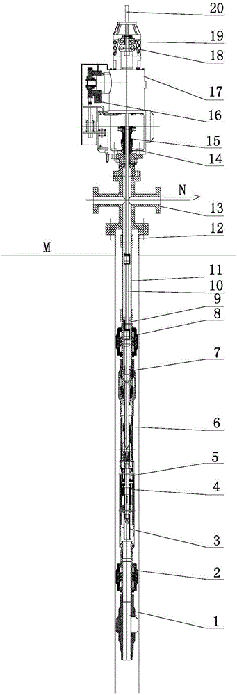
The invention belongs to the technical field of petroleum production of petroleum wells, and particularly relates to a lifting device for a petroleum production vane pump of a petroleum well. The lifting device comprises a single-plate anchor, a pump straightener, a sand spinner, a vane pump body, a sand settler, a spline transmission barrel assembly, a high temperature gas injection valve, a sucker rod, a petroleum pipe, a wellbore sleeve, a Christmas tree, a driving head and a polish rod, wherein the wellbore sleeve is arranged below the ground surface; the single-plate anchor, the pump straightener, the sand spinner, the vane pump body, the sand settler, the spline transmission barrel assembly, the high temperature gas injection valve and the petroleum pipe which are connected in sequence from bottom to top are arranged in the wellbore sleeve; the sucker rod is inserted into the petroleum pipe, and the lower end of the sucker rod is connected with the high temperature gas injection valve; the Christmas tree is located above the ground surface; the polish rod is inserted into the Christmas tree, and is connected with the upper end of the sucker rod; the polish rod is connected with the driving head and can be driven by the driving head to rotate. The lifting device for the petroleum production vane pump of the petroleum well is applicable to thermal recovery of thin petroleum, thick petroleum and high pour point petroleum and does not have gas locking in a high temperature gas-containing well; for sand-containing well, a sand spinning filter is arranged below the pump, so that the use range is wide.

Description

technical field [0001] The invention belongs to the technical field of petroleum oil production, and in particular relates to a lifting device for a vane pump for petroleum production. Background technique [0002] China National Petroleum Corporation summed up the oil production equipment. From the end of the 1970s to the present, all oil production equipment has been continuously improved and updated for more than 40 years. Only the oil production lifting equipment has not been improved or replaced by new products. It still uses reciprocating Oil production pumps, screw pumps, centrifugal oil production pumps, etc. Reciprocating pumps have been used for more than 100 years, accounting for 80% of domestic oil production equipment. Reciprocating pumps have a large area on the ground, and are subject to alternating loads of up and down reciprocating motions, resulting in large mechanical losses and low pump efficiency. For gas-bearing high-temperature oil wells, gas lock is ...

Claims


Application Information

Patent Timeline
Patent Type & Authority Applications(China)
IPC IPC(8): E21B43/24E21B34/12E21B23/01E21B43/38F04C2/344F04C13/00F04C15/00
CPCE21B23/01E21B34/12E21B43/126E21B43/24E21B43/38F04C2/3446F04C13/008F04C15/00F04C2240/50F04C2240/20
Inventor 王金强张明亮雷德荣
Owner 丹东纳泰石油机械有限公司
Why Eureka
Try Eureka