Rotary fire grate

A technology of rotating grate and rotating shaft, applied in the direction of rotary grate, grate, shaking grate, etc., can solve the problems of reduced biomass fuel gasification efficiency, worn equipment, low cleaning efficiency, etc., and achieves compression of the overall shape Size, saving combustion space, increasing temperature effect

Pending Publication Date: 2017-05-24
潘汉祥
View PDF6 Cites 9 Cited by
  • Summary
  • Abstract
  • Description
  • Claims
  • Application Information

AI Technical Summary

Problems solved by technology

[0003] One of the problems existing in the existing biomass gasification technology is that the ash accumulated in the combustion is easy to slag and is corrosive. Biomass generally contains relatively high alkali metal (Na, K, Ca, Mg) elements and non-metal (Si, S, Cl, P) elements, they can reduce the ash melting point, lead to ash accumulation and slagging, which will bring great trouble to the combustion process, not only affect the heat transfer efficiency, but also corrode and wear equipment
[0004] Most of the existing grates use a grate structure with holes. When working, the ash deposited on the gra...

Method used


Image

  • Rotary fire grate
  • Rotary fire grate
  • Rotary fire grate

Examples


Embodiment Construction

[0018] The present invention will be further described below in conjunction with embodiment, but is not limited to the content on the description.

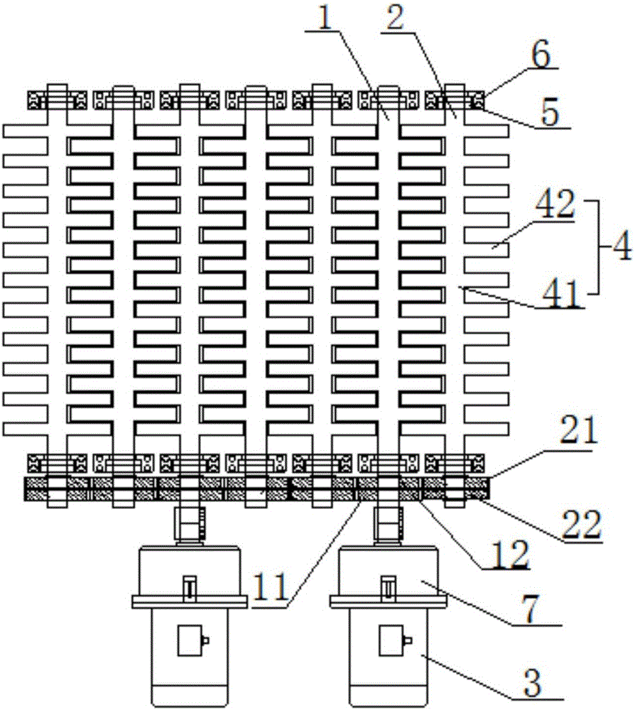
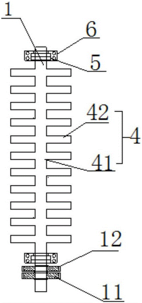
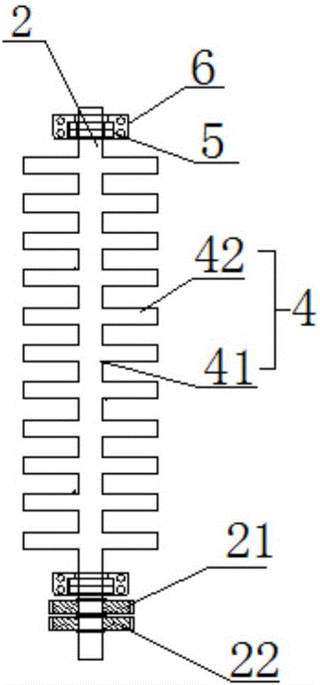
[0019] Such as figure 1 A rotary grate is shown, which includes a mounting seat, a shaft plate group A1, a shaft plate group B2 and a drive motor 3 respectively connected to the shaft plate group. The shaft plate group A and the shaft plate group B include toothed shaft plates 4 and gears, the toothed shaft plates 4 of the shaft plate group A and the shaft plate group B are arranged at intervals; the toothed shaft plate 4 is composed of a rotating shaft 41 and a toothed plate 42 arranged in a symmetrical array along the axis of the rotating shaft, which is welded or cast into an integral structure.

[0020] The toothed plates 42 of the adjacent two toothed shaft plates 4 are misaligned and leave gaps, the distance between the adjacent two toothed shaft plates 4 is greater than the length of the toothed plates 42, and the distance...


PUM


Abstract

The invention discloses a rotary fire grate. The rotary fire grate comprises installing bases, shaft plate sets A, shaft plate sets B and drive motors connected with the shaft plate sets A and the shaft plate sets B correspondingly. Tooth-shaped shaft plates of the shaft plate sets A and the shaft plate set B are distributed at intervals. The two ends of all the tooth-shaped shaft plates are connected to the corresponding installing bases in a pivoted mode. The tooth-shaped shaft plates are composed of rotary shafts and tooth-shaped plate bodies distributed in the axial directions of the corresponding rotary shafts symmetrically in an arrayed mode. A gear is fixed to the tooth-shaped shaft plate rotary shaft of each shaft plate set, and the tooth-shaped shaft plate rotary shaft of each shaft plate set is movably sleeved with a transition gear, wherein the gear is in engaged transmission with the transition gear. According to the rotary fire grate, stove ash and slag deposited after fuel combustion are timely cleared away, the single set of drive motors are used for repeatedly driving the tooth-shaped shaft plates to horizontally rotate around the corresponding shafts to form part of neutral positions, the phenomenon that integral fuel caving is caused and consequentially heat imbalance in a furnace is caused is avoided, and continuous operation of the combustion furnace is guaranteed through intermittent and intervallic rotation of the tooth-shaped shaft plates and timed instantaneous slag-discharging; and the space occupied by the fire grate is small during the static status or operating status of the fire grate, the overall appearance size of the combustion furance is compressed, and a combustion space in the combustion furnace is saved.

Description

technical field [0001] The invention belongs to the technical field of combustion furnace equipment component structure, and in particular relates to a rotary grate used in a biomass briquette fuel combustion furnace. Background technique [0002] Generally, crop straw and sawdust have the disadvantages of looseness, low density, and low calorific value per unit volume. It is inconvenient to use as fuel, resulting in a large amount of crop straw being discarded. Biomass fuel molding technology effectively solves this problem and can Change the combustion characteristics of wood chips, straw and other biomass to achieve fast, clean and efficient combustion. Biomass briquette fuel briquette technology is to compress loose and finely divided straw and agricultural waste into dense granular fuel through crushing, drying, mechanical pressing and other processes, and its energy density is about ten times higher than that before processing. This kind of biomass molding technology ...

Claims


Application Information

Patent Timeline
IPC IPC(8): F23H9/00
CPCF23H9/00
Inventor 潘汉祥
Owner 潘汉祥
Why Eureka
Try Eureka