Laser projection system

A laser projection and laser technology, applied in the field of projection display, can solve the problems of reducing user viewing experience, deterioration of projected image quality, dizziness and discomfort, etc., and achieve the effects of improving speckle dissipation effect, eliminating speckle effect, and diversifying angles

Inactive Publication Date: 2017-05-24
HISENSE
View PDF6 Cites 19 Cited by
  • Summary
  • Abstract
  • Description
  • Claims
  • Application Information

AI Technical Summary

Problems solved by technology

[0003] The high coherence of laser also brings the speckle effect in laser projection display. Speckle is that when a coherent light source irradiates a rough object, the scattered light will interfere in space because of its same wavelength and constant phase. Some parts of the space have interference and constructive effects, and some parts hav

Method used


Image

  • Laser projection system
  • Laser projection system
  • Laser projection system

Examples


Embodiment 1

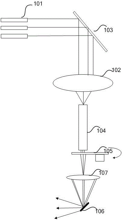
[0047] see Figure 1A , is a schematic diagram of the optical architecture of the laser projection provided by the embodiment of the present application.

[0048] The optical architecture of a laser projection system provided by an embodiment of the present invention includes: a laser 101, and a diffuse scattering phase plate 103. In this example, the diffuse scattering phase plate is a vibrating reflective phase plate for example. 102 , a homogenizing component 104 , a moving diffuser 105 , a converging lens 107 , and a light valve 106 .

[0049] laser beam in Figure 1A The transmission paths in the optical architecture shown are as follows:

[0050] The laser beam emitted by the laser 101 is incident on the vibrating reflective phase plate 103. In the above process, the laser beam emitted by the laser 101 usually requires some collimating or converging components to form a smaller spot and enter the vibrating reflective phase plate 103. Figure 1A not shown in

[0051]Afte...

Embodiment 2

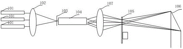
[0080] Different from Embodiment 1, in this example, the diffuse scattering phase plate is a fixed phase plate, and partitions are set on the diffusion sheet, and different partitions have different divergence angles for the laser beam.

[0081] Specifically, see Figure 1B , is a schematic diagram of the optical architecture of the laser projection provided by the embodiment of the present application. The optical structure includes: a laser group 101 , a focusing lens 102 , a fixed phase plate 103 , a homogenizing component 104 , a moving diffuser 105 , and a light valve 106 .

[0082] Specifically, the laser group 101 emits a laser beam of at least one color. For simplicity, in this example, the laser group 101 emits a laser beam of one color as an example, which can be a blue laser, or a red laser or a green laser. laser.

[0083] The laser beam spot size emitted by the laser group is usually large. In order to improve the optical utilization of the optical components be...

Embodiment 3

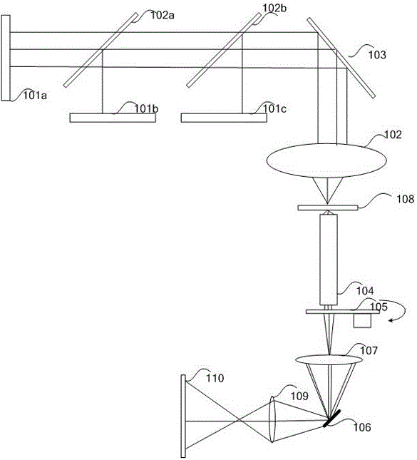
[0100] In this embodiment, the diffuse scattering phase plate can be specifically divided into two types, that is, the basic modification obtained by combining Embodiment 1 and Embodiment 2 Figure 1C scheme shown. Specifically, in Figure 1A Basically, the diffuse scattering phase plate can be the vibrating mirror 103 , and a first phase plate 108 is also arranged between the vibrating mirror 103 and the light entrance of the light rod 104 . In this example, the first phase plate 108 may specifically be a transmission type phase plate, and is fixedly arranged. The setting of the first phase plate 108 can refer to the second embodiment Figure 1B description of.

[0101] exist Figure 1C The laser projection system shown specifically includes: a laser 101a, a laser 101b, and a laser 101c, which respectively emit laser beams, a first light-combining lens 102a, and a second light-combining lens 102b. The laser beams emitted by the above-mentioned lasers pass through the two ...


PUM


Abstract

The invention discloses a laser projection system comprising a laser light source which emits laser beams of at least one color. The transmission light path of the laser beams includes a light homogenizing part which is used for receiving and homogenizing the laser beams; a light valve which is used for receiving the laser beams homogenized by the light homogenizing part and modulating the laser beams; a diffuse scattering phase plate which is arranged at the light incident surface side of the light homogenizing part and can increase the divergence angle of the beams; and a moving diffuser which is arranged at the light emergent surface side of the light homogenizing part and can greatly enhance the generation number of random phases, wherein the position of the moving diffuser is the object plane position of the light valve and the human eye integration effect is performed on the generated random phases so that the speckle effect of the projection frame can be weakened or eliminated to the greatest extent, and thus the speckle elimination effect and the display quality of the projection frame can be greatly enhanced.

Description

technical field [0001] The present application relates to the field of projection display, in particular to a laser projection system. Background technique [0002] Laser is a light source with high brightness, strong directionality, and monochromatic coherent light beam. As an excellent coherent light source, laser light source has the advantages of good monochromaticity, strong directionality, and high luminous flux. Projection display technology field. [0003] The high coherence of laser also brings the speckle effect in laser projection display. Speckle is that when a coherent light source irradiates a rough object, the scattered light will interfere in space because of its same wavelength and constant phase. Some parts of the space have interference and constructive effects, and some parts have interference and destructive effects. The final result is granular light and dark spots on the screen. These unfocused spots appear to be in a flickering state to the human eye...

Claims


Application Information

Patent Timeline
IPC IPC(8): G03B21/20G02B27/48
CPCG02B27/48G03B21/2013G03B21/2033G03B21/206G03B21/208
Inventor 田有良李巍刘显荣
Owner HISENSE
Why Eureka
Try Eureka