Permanent magnet synchronous motor for compressor

A synchronous motor, permanent magnet technology, applied to synchronous motors with stationary armatures and rotating magnets, synchronous machines, synchronous machine parts, etc. Motor efficiency and other issues, to achieve the effect of improving noise, improving efficiency, and reducing motor cogging torque

Pending Publication Date: 2017-05-24
广东志高精密机械有限公司
View PDF7 Cites 17 Cited by
  • Summary
  • Abstract
  • Description
  • Claims
  • Application Information

AI Technical Summary

Problems solved by technology

However, the use of rare earth NdFeB materials with high remanence, in compressors equipped with air conditioners, refrigerators, etc., has the problem of increased noise in the middle and low frequency bands.
Secondly, due to the rapid development of modern power electronics technology, the current output by the controller used in the motor drive has been able to achieve a sinusoidal waveform, and only the fundamental wave component plays an effective role in the torque, thus requiring the induction in the motor stator winding The voltage should be as sinusoidal as possible, and its high-frequency components will affect the torque fluctuation, which will increase the noise and vibration. Since the voltage induced in the stator winding will form a distortion component containing many high-order harmonics, the iron loss will increase and the efficiency of the motor will be reduced.

Method used


Image

  • Permanent magnet synchronous motor for compressor
  • Permanent magnet synchronous motor for compressor
  • Permanent magnet synchronous motor for compressor

Examples


Embodiment 1

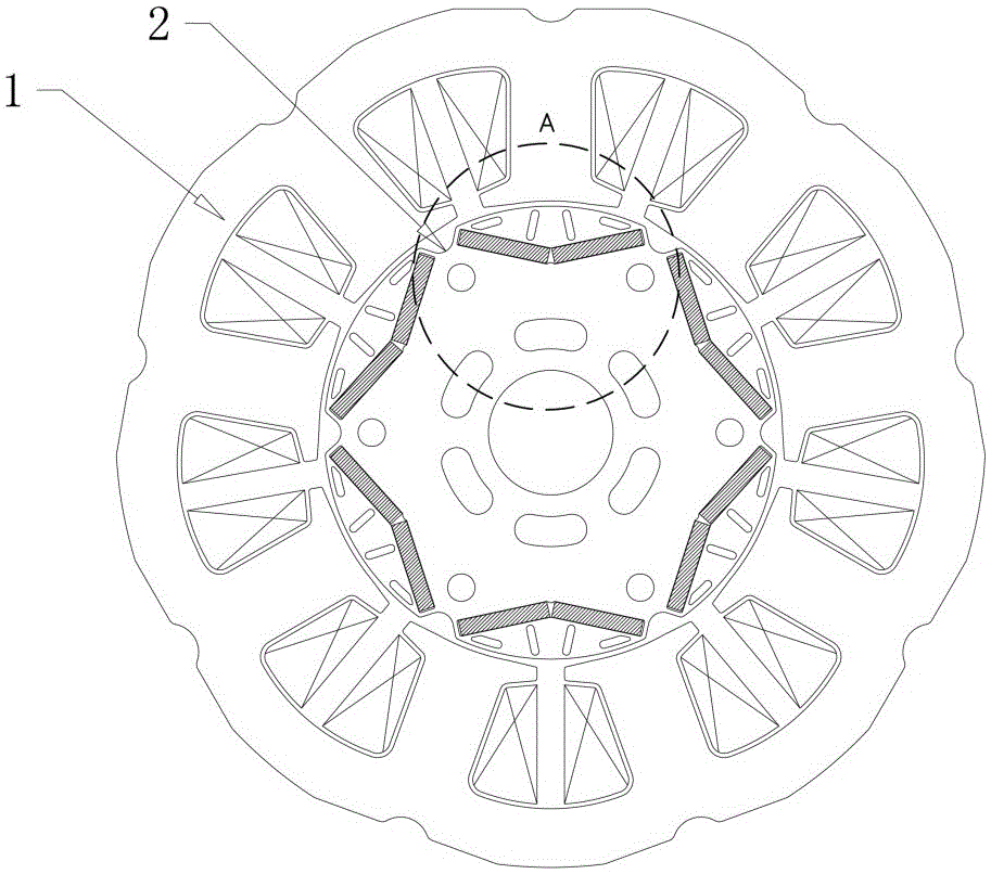
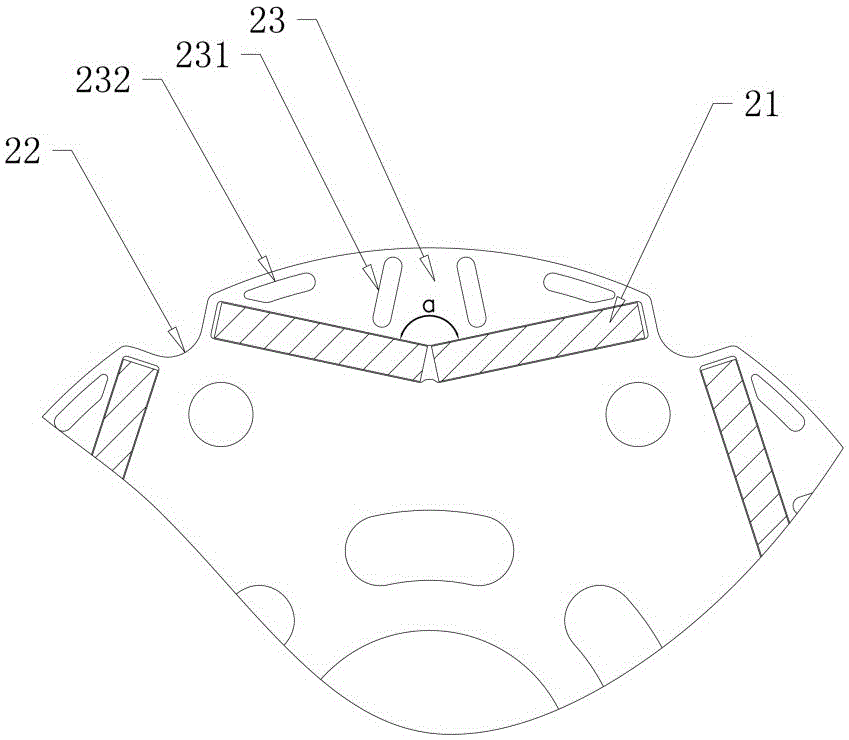
[0018] See attached figure 1 And attached figure 2 As shown, in this embodiment, a permanent magnet synchronous motor used in a compressor includes a stator 1 and a rotor 2 composed of laminated electromagnetic steel plates, wherein, according to the specifications of the permanent magnet synchronous motor, different thicknesses are selected. Electromagnetic steel plate, the thickness of the common electromagnetic steel plate used for motors is 0.3~0.5mm. The rotor 2 is set inside the stator 1 and there is an air gap between the stator 1 and the rotor 2; the end surface of the rotor 2 is provided with a plurality of magnet accommodation grooves 21 in a "V" shape distributed in the circumferential direction and extending along the length direction of the rotor 2 , wherein, the angle between the two sides of the magnet accommodating groove 21 faces the outer diameter of the rotor 2; the angle α between the two sides of the magnet accommodating groove 21 is 90°-170°. Permanent...

Embodiment 2

[0022] See attached Figure 5 As shown, in this embodiment, the difference from Embodiment 1 is that there are two sets of first slit hole groups 231, wherein the two sets of first slit hole groups 231 each include two The axis of symmetry is symmetrically distributed in the first slot holes in the middle of the slot part 23; in this way, multiple sets of first slot hole groups 231 are set on the slot part 23, so that the magnetic flux in the air gap part between the stator 1 and the rotor 2 The density distribution is smoother in the circumferential direction, thereby reducing the noise and vibration of the permanent magnet synchronous motor.


PUM


Abstract

The invention discloses a permanent magnet synchronous motor, comprising a stator and a rotor which are formed by laminating electromagnetic steel plates, wherein the rotor is arranged inside the stator, a plurality of magnet accommodating slots extending in the length direction of the rotor and distributed circumferentially in a V-shaped structure are formed in the end face of the rotor, permanent magnets having the same magnetic poles are arranged in the magnet accommodating slots, and meanwhile, permanent magnets having opposite magnetic poles are arranged in any two adjacent magnet accommodating slots; an arc groove extending in the length direction of the rotor is formed in the outer circumferential surface of the rotor between any two adjacent magnet accommodating slots; at least one first gap hole group and one second gap hole group extending in the length direction of the rotor are formed in a gap part between the outer side of each magnet accommodating slot and the outer circumference of the rotor; thus, the magnetic flux density distribution of the air gap part between the stator and the rotor is smoothed circumferentially, and then noise and vibration of the permanent magnet synchronous motor are reduced.

Description

technical field [0001] The invention relates to the technical field of synchronous motors, in particular to a permanent magnet synchronous motor used in compressors. Background technique [0002] At present, in the permanent magnet synchronous motor with 3n (n=1,2,3...) slots in the motor stator and 2n (n1,2,3...) poles in the rotor, the stator winding adopts concentrated winding and excitation Rare earth NdFeB permanent magnets are used to achieve high efficiency of the motor. However, the use of rare earth NdFeB materials with high remanence has the problem of increased harsh mid- and low-frequency noise in compressors equipped with air conditioners and refrigerators. Secondly, due to the rapid development of modern power electronics technology, the current output by the controller used in the motor drive has been able to achieve a sinusoidal waveform, and only the fundamental wave component plays an effective role in the torque, thus requiring the induction in the motor ...

Claims


Application Information

Patent Timeline
Patent Type & Authority Applications(China)
IPC IPC(8): H02K21/14H02K21/02H02K1/27
CPCH02K1/2773H02K21/028H02K21/145H02K2213/03H02K2201/03
Inventor 蔡水旺杨泽宇
Owner 广东志高精密机械有限公司
Why Eureka
Try Eureka