Eureka AIR delivers breakthrough ideas for toughest innovation challenges, trusted by R&D personnel around the world.

Middle frame component and production method thereof

A frame and component technology, applied in the field of middle frame parts and their production, can solve the problems of inability to transfer heat in time, high temperature of the middle frame parts, and high power consumption, so as to enhance the resistance to neutral salt spray corrosion, avoid The signal is not smooth and the effect of improving the user experience

Active Publication Date: 2017-05-24
HUAWEI TECH CO LTD
View PDF11 Cites 6 Cited by
  • Summary
  • Abstract
  • Description
  • Claims
  • Application Information

AI Technical Summary

Problems solved by technology

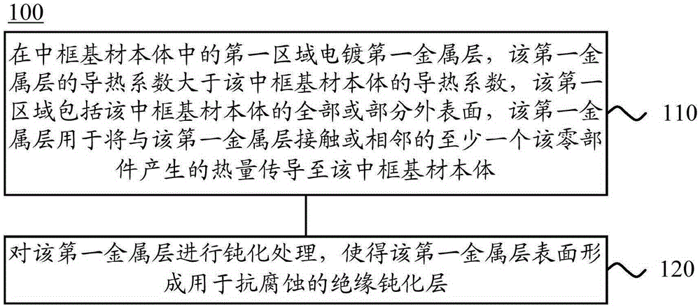
[0002] With the development of electronic products, the demand for heat dissipation of electronic products is getting higher and higher. The materials of the middle frame parts of existing electronic products have gradually been unable to meet the current heat dissipation requirements. For example, the current middle frame materials of mobile phones have gradually been unable to meet The current heat dissipation requirements, especially the mobile phone chip area with relatively large power consumption, generate a large amount of heat, resulting in excessive temperature in some parts of the middle frame. The existing materials commonly used in the middle frame of mobile phones are die-casting magnesium alloy, stainless steel, and die-casting aluminum. Alloy and die-cast zinc alloy have a thermal conductivity between 10 and 160W / m.k, which cannot conduct heat quickly, so that the heat in the local high-temperature area of ​​the middle frame cannot be transferred to the low-temperature area in time, and thus cannot effectively reduce the local temperature. The temperature at a high temperature location cannot meet the current application requirements for mobile phone heat dissipation

Method used


Image

  • Middle frame component and production method thereof
  • Middle frame component and production method thereof
  • Middle frame component and production method thereof

Examples


Embodiment Construction

[0167] The following will clearly and completely describe the technical solutions in the embodiments of the present invention with reference to the drawings in the embodiments of the present invention. Obviously, the described embodiments are part of the embodiments of the present invention, not all of them. Based on the embodiments of the present invention, all other embodiments obtained by persons of ordinary skill in the art without making creative efforts shall fall within the protection scope of the present invention.

[0168] It should be understood that the middle frame in the embodiment of the present invention is a component used to support the electronic product inside the electronic product. In other words, the middle frame can be used to fix, place, accommodate or support the components of the electronic product. For example, the middle frame can be a support member for placing PCB boards, chips or batteries in electronic products, or the middle frame can be a suppo...


PUM


Abstract

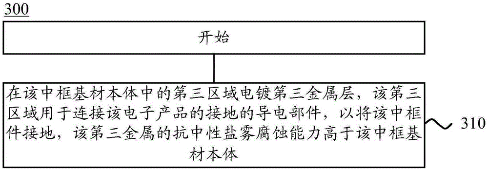
Embodiments of the invention provide a middle frame component and a production method thereof. The middle frame component is a support component which is in an electronic product and is used for supporting components of the electronic product. The middle frame component comprises a middle frame base material body, a first metal layer and an insulation passivation layer, wherein the first metal layer is attached to a first area of the middle frame base material body; a heat conductivity coefficient of the first metal layer is greater than a heat conductivity coefficient of the middle frame base material body; the first area includes all or parts of external surfaces of the middle frame base material body; the first metal layer is used for conducting heat generated by at least one component which is contacted with or adjacent to the first metal layer to the whole first metal layer and the middle frame base material body; and the insulation passivation layer is attached to a surface of the first metal layer. In the embodiments of the invention, heat dissipation performance of the middle frame component can be increased.

Description

technical field [0001] The invention relates to the communication field, in particular to a middle frame and a production method thereof. Background technique [0002] With the development of electronic products, the demand for heat dissipation of electronic products is getting higher and higher. The materials of the middle frame parts of existing electronic products have gradually been unable to meet the current heat dissipation requirements. For example, the current middle frame materials of mobile phones have gradually been unable to meet The current heat dissipation requirements, especially the mobile phone chip area with relatively large power consumption, generate a large amount of heat, resulting in excessive temperature in some parts of the middle frame. The existing materials commonly used in the middle frame of mobile phones are die-casting magnesium alloy, stainless steel, and die-casting aluminum. Alloy and die-cast zinc alloy have a thermal conductivity between ...

Claims


Application Information

Patent Timeline
IPC IPC(8): H05K7/20
CPCH05K7/2039H05K7/20H05K7/20445H05K9/0064G06F1/1656G06F1/203H04M1/026H05K7/20509
Inventor 蔡明胡邦红李龙雨
Owner HUAWEI TECH CO LTD
Why Eureka
Eureka Blog
Learn More