
A push-bending forming method for l-shaped thin-walled aluminum alloy elbow with small curvature bending radius

A technology with bending radius and small curvature, which is applied in the field of push-bending of L-shaped thin-walled aluminum alloy elbows with small curvature radius, can solve the problems of inability to transfer smoothly, increase production cycle, increase cost, etc., to improve material flow, The effect of improving the forming efficiency and slowing down the flow of the outer material

Active Publication Date: 2018-05-29
NANCHANG HANGKONG UNIVERSITY
View PDF10 Cites 2 Cited by
  • Summary
  • Abstract
  • Description
  • Claims
  • Application Information

AI Technical Summary

Problems solved by technology

The length of the tube blank of this part is obviously greater than πD or πR, and basically reaches or exceeds 2πD. At this time, even if the material is beveled before and after the tube blank, the material cannot be smoothly transferred due to the long distance from the inner side of the tube tail close to the pusher to the bending part. The groove of the pipe tail disappears, which inevitably produces serious wrinkles on the inner side of the elbow. At present, such parts are often welded by 90° elbow welding straight pipe or half pipe stamping and welding, which increases the production cycle and improves the quality of the pipe. cost

Method used


Image

  • A push-bending forming method for l-shaped thin-walled aluminum alloy elbow with small curvature bending radius
  • A push-bending forming method for l-shaped thin-walled aluminum alloy elbow with small curvature bending radius
  • A push-bending forming method for l-shaped thin-walled aluminum alloy elbow with small curvature bending radius

Examples


Embodiment Construction

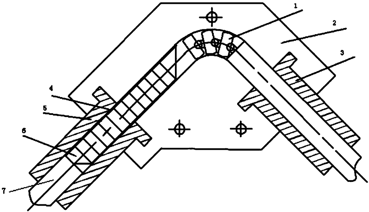
[0028] The technical solution in the embodiment of the present invention will be clearly and completely described below in conjunction with the accompanying drawings in the embodiment of the present invention. Obviously, the tube blank in the described embodiment is a thin-walled aluminum alloy tube blank, which is only the embodiment of the present invention. Some, but not all, embodiments. Based on the embodiments of the present invention, all other embodiments obtained by persons of ordinary skill in the art without making creative efforts belong to the protection scope of the present invention.

[0029] The object of the present invention is to provide a push-bending forming method of an L-shaped thin-walled aluminum alloy elbow with a small curvature radius, which can push-bend a pipe fitting with a long straight pipe section at one end of a pipe elbow with a small curvature radius.

[0030] In order to make the above objects, features and advantages of the present invent...


PUM

PropertyMeasurementUnit
thicknessaaaaaaaaaa
hardnessaaaaaaaaaa

Abstract

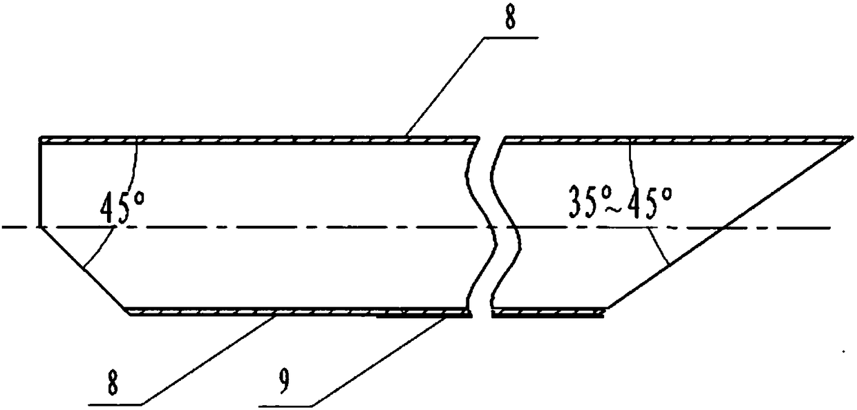
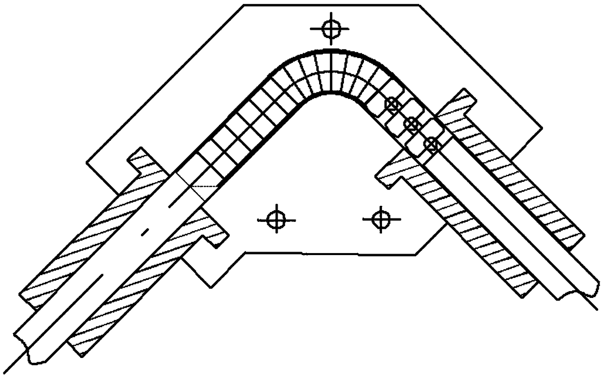
The invention discloses a push-bending forming method of an L-shaped thin-walled aluminum alloy elbow pipe with a small curvature radius. By bending a long pipe blank of an aluminum alloy thin-walled pipe blank, the inner two ends are beveled at 35° to 45°. And apply a protective agent on the outside of the tube blank, spray oily molybdenum disulfide on the semi-cylindrical surface of the inner front part of the tube blank and the area πD away from the front part, which is beneficial to the material flow inside the tube bending and improve wrinkling; and replace the original Some polyurethane round rods are filled with several polyurethane cylindrical blocks inside the pushed end of the tube blank, which is easier to take out after forming than the integral polyurethane filler rod, which improves the forming efficiency. At the same time, the polyurethane cylindrical block with appropriate hardness, thickness and diameter is conducive to the internal support of the elbow, and is not easy to cause wrinkles on the inner side of the bend; during the forming process, the thrust of the core head is increased, and the filler provides sufficient internal pressure in the pipe to force the material to slope forward. A large amount of flow at the mouth, so as to avoid wrinkling, and form qualified L-shaped thin-walled aluminum alloy pipe fittings with small curvature bending radius.

Description

technical field [0001] The invention relates to the technical field of pipe bending, in particular to a push-bending method for an L-shaped thin-walled aluminum alloy elbow with a small curvature radius. Background technique [0002] Pipe push bending is a bending method that pushes the tube blank with filler inside into the bending mold for forming. It is generally used to form a 90° pipe bend whose relative bending radius R is less than 1 times the pipe diameter D (R≦D) Head, that is, except for the 90° arc section of the pipe elbow, there are basically no straight pipe sections at both ends. This is because the pipe fittings with less than 1 times the relative bending radius are prone to wrinkling on the inside and cracking on the outside, so it is difficult to bend pipes less than 1 times the relative bending radius in other existing pipe bending methods. At present, the pipe is push-bent to form a pipe fitting with a relative bending radius of 1 times. The length of th...

Claims


Application Information

Patent Timeline
Patent Type & Authority Patents(China)
IPC IPC(8): B21D9/12B21D9/16
CPCB21D9/125B21D9/16
Inventor 徐雪峰付春林孙前江朱永国王高潮徐欧平
Owner NANCHANG HANGKONG UNIVERSITY
Learn More