A tube coiler and method for coiling a separation column

A separation column and tube rolling machine technology, applied in the field of machining, can solve the problems of coiling spiral tubes and the inability to arrange the coils of spiral objects closely, and achieve the effects of low cost, simple structure, and easy operation

Active Publication Date: 2019-06-04
MATERIAL INST OF CHINA ACADEMY OF ENG PHYSICS
View PDF9 Cites 0 Cited by
  • Summary
  • Abstract
  • Description
  • Claims
  • Application Information

AI Technical Summary

Problems solved by technology

[0005] The purpose of the present invention is to overcome the existing coiling machine in the prior art that can only roll a circle of hollow straight tubes, and cannot roll it into a spiral tube. Although the existing coiling machine can roll a spiral Shaped objects, but its function and structure are designed taking into account the characteristics of the rolled product, that is, the spring. The rolled product has elasticity and severe rebound, and it is impossible to make the two adjacent rings of the spiral object tightly In view of the above-mentioned deficiencies of the arrangement, a coiler and method for coiling a separation column are provided

Method used


Image

  • A tube coiler and method for coiling a separation column
  • A tube coiler and method for coiling a separation column
  • A tube coiler and method for coiling a separation column

Examples


Embodiment 1

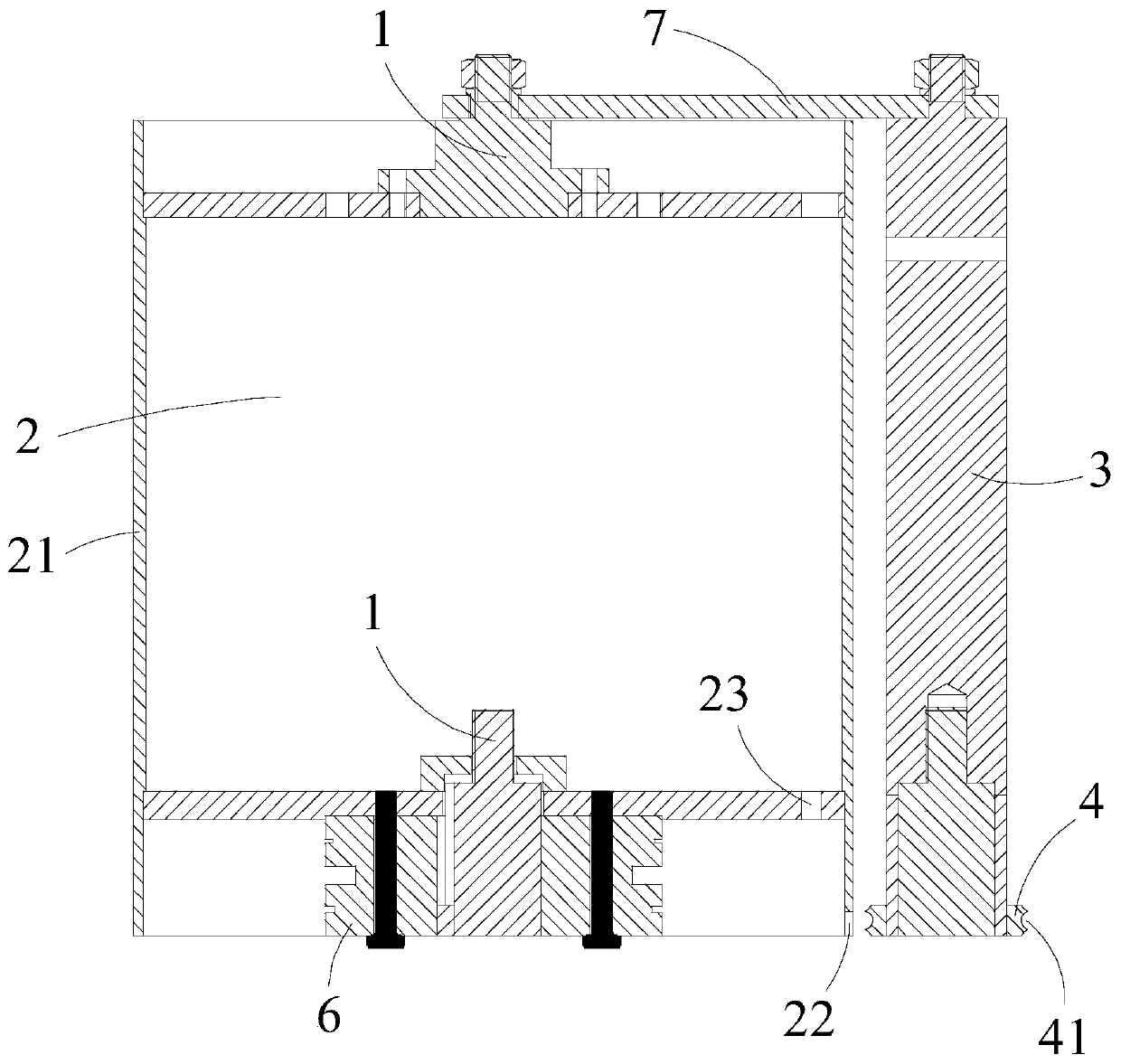
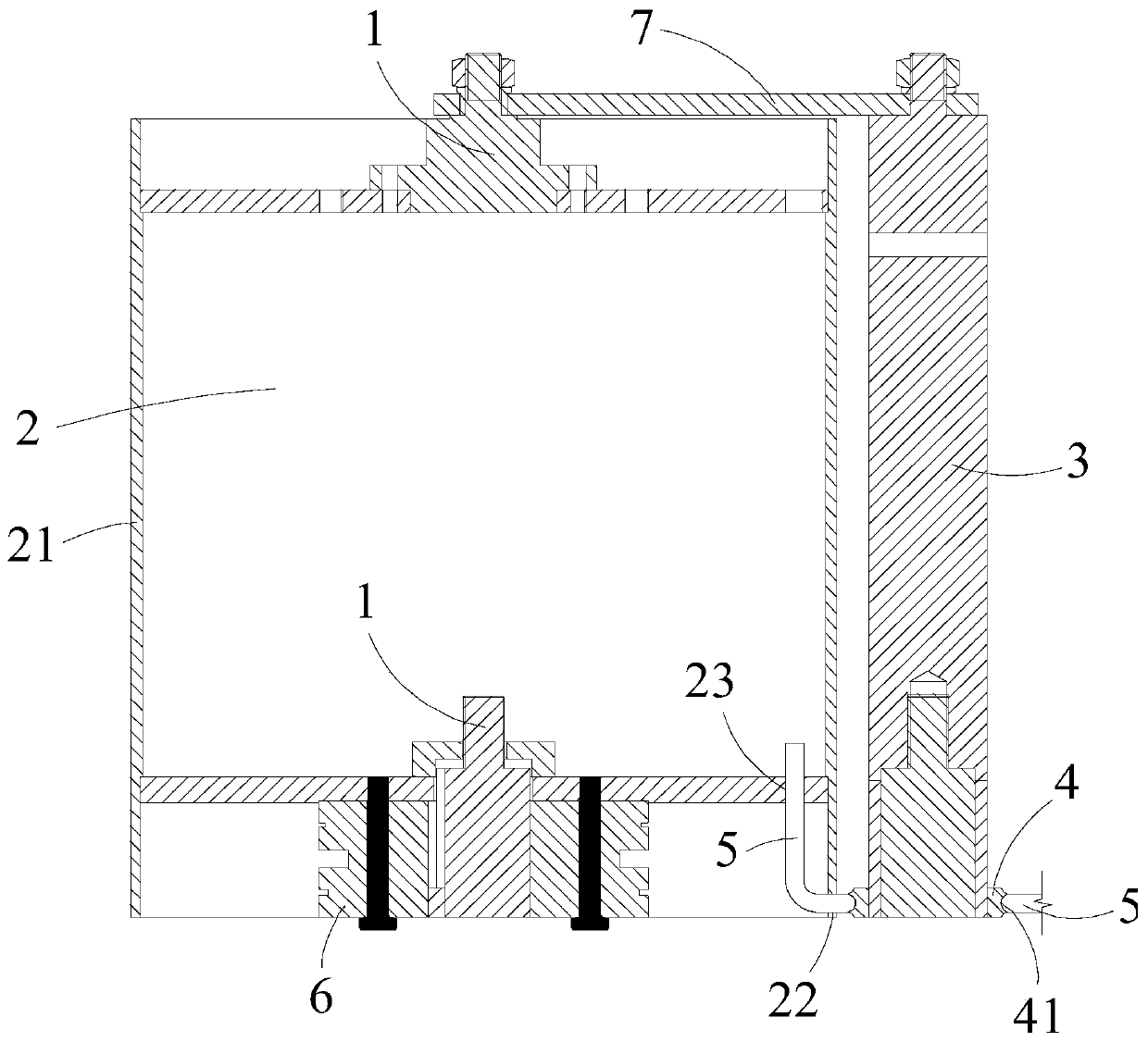
[0049] Such as Figure 1-3 As shown, a pipe coiler for rolling a separation column according to the present invention includes a frame, and the frame is provided with a rotating shaft 1, and also includes:

[0050] The rolling module 2 is rotatably connected to the rotating shaft 1, and includes a sleeve 21 and a bayonet port 1 22, the sleeve 21 is used for winding the hollow straight pipe 5 on its side wall, and the bayonet port 1 22 is used for fixing One end of the hollow straight pipe 5, the card interface 1 22 is arranged on the side wall of the sleeve 21;

[0051] The driving device is connected to the rolling module 2 and drives it to rotate around the rotating shaft 1;

[0052] The guide shaft 3 is arranged parallel to the rotating shaft 1;

[0053] The guide wheel 4 is slidably arranged on the guide shaft 3 and rotates around the guide shaft 3 . The guide wheel 4 is provided with a guide groove 41 , and the guide groove 41 is adapted to the hollow straight pipe 5 . ...

Embodiment 2

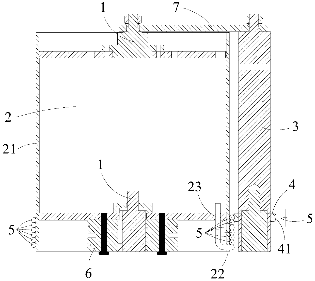
[0060] Such as Figure 1-3 As shown, a method for rolling a separation column according to the present invention uses a tube coiler for rolling a separation column as described in Example 1, which is characterized in that it includes the following steps:

[0061] A. Fix one end of the hollow straight pipe 5 to the card interface one 22, and the body of the hollow straight pipe 5 is adapted to the guide groove 41;

[0062] B. Start the driving device, and the hollow straight pipe 5 is wound on the sleeve 21 to form a helical pipe;

[0063] C, welding the rings formed by the hollow straight tubes 5 of the two adjacent plates;

[0064] D. The spiral tube is demoulded.

[0065] As a preferred solution of this embodiment, the step C is implemented while the step B is implemented.

[0066] Using a method for rolling a separation column according to the present invention, through the mutual cooperation of the rolling module 2, the driving device, the guide shaft 3 and the guide wh...


PUM


Abstract

The invention discloses a pipe winding machine for winding separation columns and a method. The pipe winding machine comprises a rack and further comprises winding modules, a drive device, a guide shaft and a guide wheel. A rotary shaft is arranged on the rack. The winding modules are rotatably connected to the rotary shaft and each comprises a sleeve and a first clamping opening. A hollow straight pipe is wound around the side wall of each sleeve. Each first clamping opening is used for fixing one end of the corresponding hollow straight pipe. The first clamping openings are formed in the side walls of the corresponding sleeve. The drive device is connected with the winding modules and drives the winding modules to rotate around the rotary shaft. The guide shaft is fixedly arranged relative to the rotary shaft. The guide wheel is slidably arranged on the guide shaft and rotates around the guide shaft. A guide groove is formed in the guide wheel. The guide groove is matched with the hollow straight pipes. By the adoption of the pipe winding machine, the problems that an existing winding machine only can achieve one circle of winding, and spiral pipes cannot be wound; and an existing spring coiling machine can wind spiral objects, but wound products rebound seriously, and adjacent two coils of circular rings cannot be tightly arranged in the prior art can be solved effectively. Meanwhile, the pipe winding machine is simple in structure, easy and convenient to operate and low in cost.

Description

technical field [0001] The invention relates to the field of machining, in particular to a pipe coiling machine and method for coiling a separation column. Background technique [0002] Nuclear fusion reactors use deuterium-tritium as nuclear fuel, so hydrogen isotope separation is one of the core technologies of the fusion reactor nuclear fuel cycle. The effective control of the environmental release of tritium during the operation of the reactor can also be applied to the multiplication and extraction of tritium, plasma discharge and treatment, etc. [0003] When using low-temperature chromatographic hydrogen isotope separation (GC) or palladium heat displacement chromatography hydrogen isotope separation to separate a large amount of hydrogen isotopes, it is necessary to fill the hollow straight tube with molecular sieve material or palladium material to form a separation column, and the separation column is cooled to reduce the temperature. Molecular sieve materials or ...

Claims


Application Information

Patent Timeline
Patent Type & Authority Patents(China)
IPC IPC(8): B21D11/06B21D11/22
CPCB21D11/06B21D11/22
Inventor 杨莞邓立宋江锋姚勇文明喻彬胡俊陈华明殷雪峰陈克琳
Owner MATERIAL INST OF CHINA ACADEMY OF ENG PHYSICS
Why Eureka
Try Eureka