Liquor-stored tank

A technology for storing wine and tanks, which is applied in the field of wine storage tanks, and can solve the problems affecting beer's mouth-killing power, easy escape of carbon dioxide, and carbon dioxide loss, so as to achieve good cooling and fresh-keeping effects, avoid a large amount of loss, and improve the mouth-killing power Effect

Active Publication Date: 2017-05-31
杭州旷博机械设备有限公司
View PDF8 Cites 5 Cited by
  • Summary
  • Abstract
  • Description
  • Claims
  • Application Information

AI Technical Summary

Problems solved by technology

[0005] At present, the back pressure of sake tanks in domestic breweries has generally dropped from 0.3MPa in the past to below 0.08MPa. The free carbon dioxide in the wine is not easy to dissolve in the low pressure state, causing the carbon dioxide just added to the wine mixer t

Method used


Image

  • Liquor-stored tank
  • Liquor-stored tank
  • Liquor-stored tank

Examples


Example Embodiment

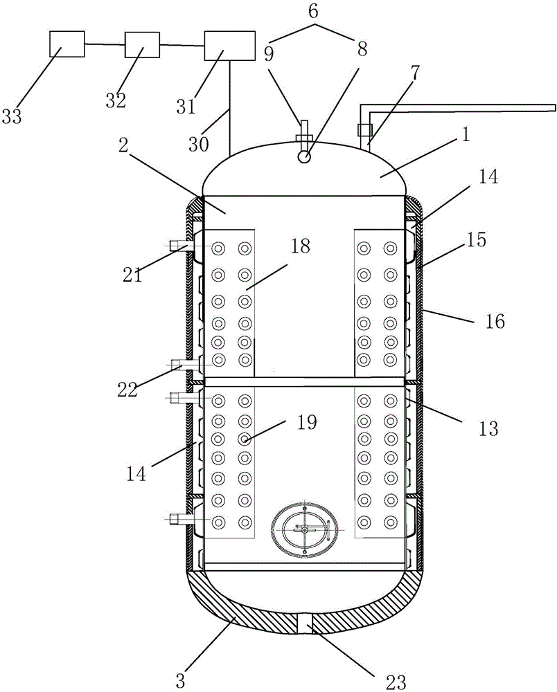
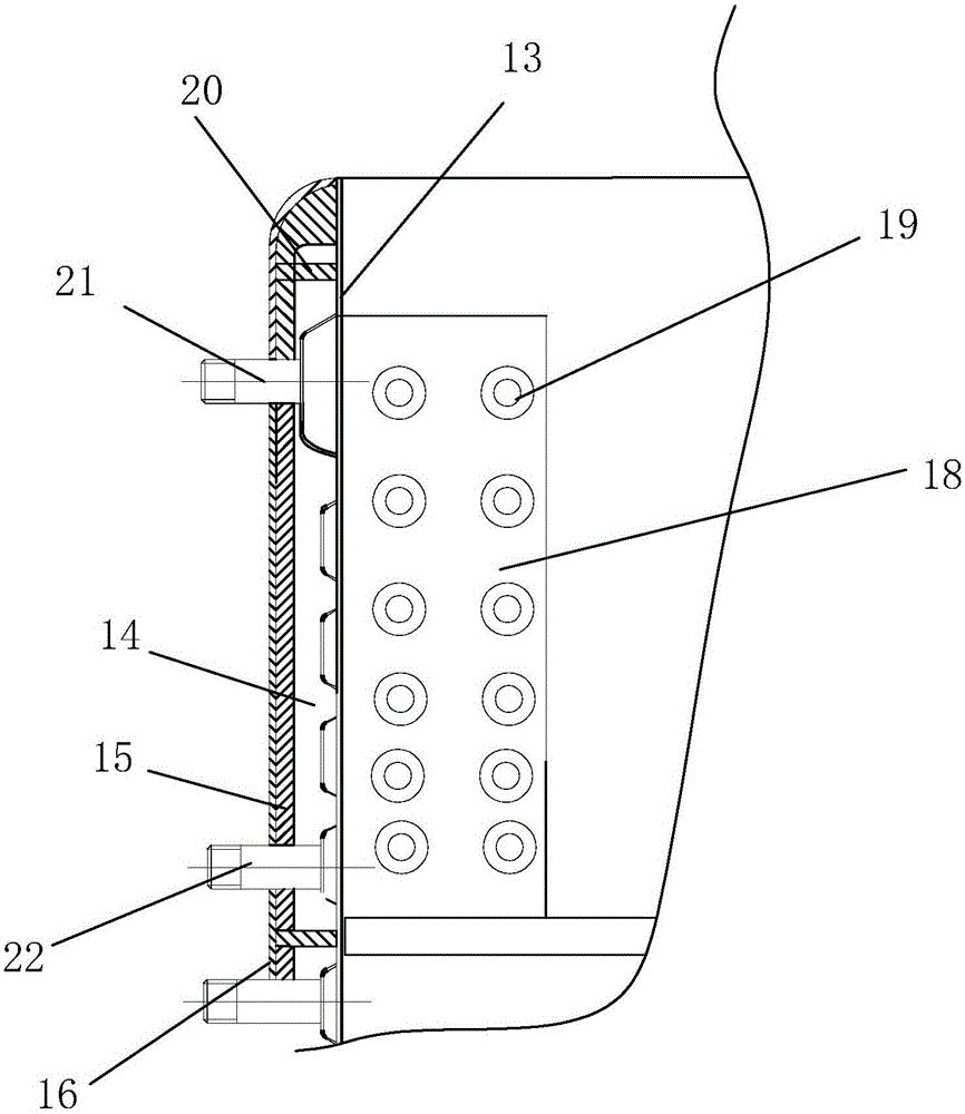
[0037] Example 1 as figure 1 and figure 2 As shown, the wine storage tank includes a tank top 1, a tank body 2 and a tank bottom 3, and the three are connected together by welding. There are four supporting feet 4, which are respectively welded on the bottom of the tank bottom 3. An elastic pad 5 is installed on the lower end of each supporting foot 4 .

[0038] The tank top 1 is in the shape of a round arch; a safety valve, a suspension ring and a cleaning device 6 are respectively installed on the top wall. The cleaning device 6 is installed at the center of the tank top 1; the filling inlet 7 is provided on one side of the cleaning device 6 . The cleaning device 6 includes a universal cleaning head 8 and a water delivery pipe 9 provided in the tank body 2; the water delivery pipe 9 is provided with an interface through which the pressure pump is connected. Also be equipped with pressure gauge on the water delivery pipe 9.

[0039] The filling inlet 7 is connected with...

Example Embodiment

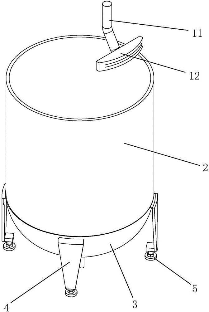
[0045] Embodiment 2 The difference between embodiment 2 and embodiment 1 is: see image 3 , inside the tank top 1, a deflector 10 is connected to the filling inlet 7. The deflector 10 includes a deflector 11 that is connected to the filling inlet 7 at one end and is inclined toward the inner wall of the tank body 2 , and a pipe head 12 that is sleeved on the other end of the deflector tube 11 and is close to or attached to the inner wall of the tank body 2 . The pipe head 12 is in the shape of a cuboid, and its water outlet end is arc-shaped, and fits with the arc of the inner wall of the tank body 2 . The beer enters from the filling inlet 7 through the pipeline, and then is output from the pipe head 12 through the draft tube 11 and flows down slowly along the inner wall of the tank body 2 .

Example Embodiment

[0046] Embodiment 3 The difference between Embodiment 3 and Embodiment 1 is: see Figure 4 The deflector 10 includes a liquid inlet pipe 24 connected to the filling inlet 7 at one end and arranged vertically downward, and a guide ring 25 connected to the liquid inlet pipe 24 and attached to the inner wall of the tank body 2 along the circumference of the tank body 2 . See Figure 5 The guide ring 25 includes a ring body 26 and a ring edge 27 extending obliquely downward along the outer edge of the ring body 26 . The ring body 26 is provided with guide grooves 28 along its radial direction. A plurality of branch channels 29 communicating with the guide groove 28 are opened on the ring edge 27 .

[0047] Beer enters the diversion groove 28 in the diversion ring 25 through the diversion pipe 11, and then flows into the branch channels 29 along the diversion groove 28;


PUM


Abstract

The invention discloses a liquor-stored tank. The liquor-stored tank comprises a tank top, a tank body and a tank bottom. The tank top is provided with a cleaning device, a safety valve and a pouring inlet. The tank body sequentially comprises an inner container, a cooling jacket, an insulating layer and an outer coating body from inside to outside. An outlet is formed in the tank bottom. The pouring inlet is connected with a fluid director capable of guiding beer to be poured in along the inner wall of the tank body. By the adoption of the liquor-stored tank, the problem that carbon dioxide gas in beer fluid is lost when beer is poured into the tank body is solved, and poor zest of the beer is avoided; and meanwhile, the liquor-stored tank achieves a high-performance fluid separation effect and a preservation effect.

Description

technical field [0001] The invention relates to the technical field of beer brewing equipment, in particular to a wine storage tank. Background technique [0002] Wine storage tanks, also known as sake tanks; that is, jars for storing fresh wine. Sake tanks are mainly used to clean beer. Self-brewed beer equipment and beer tanks are currently widely used in the beer industry. A kind of sake tanks in the wine making industry are generally collectively referred to as wine storage tanks. [0003] After the beer is fermented and mature, it is necessary to filter out the turbidity such as yeast in the fermented liquid to make the wine clear and translucent. After the fermented liquid is filtered, it is called "sake". It is supplied to the packaging department for bottling to become a finished product. Sake tanks are used to hold sake. [0004] The structure of the sake tank is a cylinder with a conical bottom. The material is usually made of stainless steel, with polyurethane i...

Claims


Application Information

Patent Timeline
IPC IPC(8): B65D90/00B65D90/02B65D88/74B65D90/48B65D90/14B65D88/54B65D85/72
CPCB65D85/72B65D88/54B65D88/744B65D90/00B65D90/0093B65D90/028B65D90/14B65D90/48
Inventor 许柳斌
Owner 杭州旷博机械设备有限公司
Why Eureka
Try Eureka