Sleeve of full-casing and full-slewing drilling machine and method for removing barriers in front of cutter head of shield tunneling machine

A technology of full-rotary drilling rig and shield cutter head, which is applied in the direction of earth drilling, mining equipment, tunnels, etc. It can solve the problems that affect the construction progress of the project, it is not suitable for removing sleeve obstacles, and the construction period is long, so as to achieve simple construction. Fast and economical, avoiding the risk of piping quicksand, and reducing construction costs

Active Publication Date: 2017-05-31
WUHAN MUNICIPAL CONSTR GROUP
View PDF5 Cites 17 Cited by
  • Summary
  • Abstract
  • Description
  • Claims
  • Application Information

AI Technical Summary

Problems solved by technology

However, both of these two processing methods have certain defects: when opening the chamber under pressure in the shield machine, it is difficult to maintain the pressure in the earth pressure chamber, and the technical level of the staff in the chamber is high; the groundwater level is high, and the shield tunneling The instability of the excavation surface and the high risk to the safety of

Method used


Image

  • Sleeve of full-casing and full-slewing drilling machine and method for removing barriers in front of cutter head of shield tunneling machine
  • Sleeve of full-casing and full-slewing drilling machine and method for removing barriers in front of cutter head of shield tunneling machine
  • Sleeve of full-casing and full-slewing drilling machine and method for removing barriers in front of cutter head of shield tunneling machine

Examples


Embodiment Construction

[0035] In order to better understand the present invention, the present invention will be further described below in conjunction with the accompanying drawings and specific embodiments.

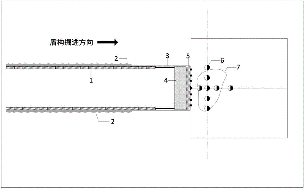
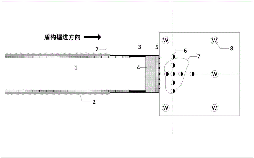
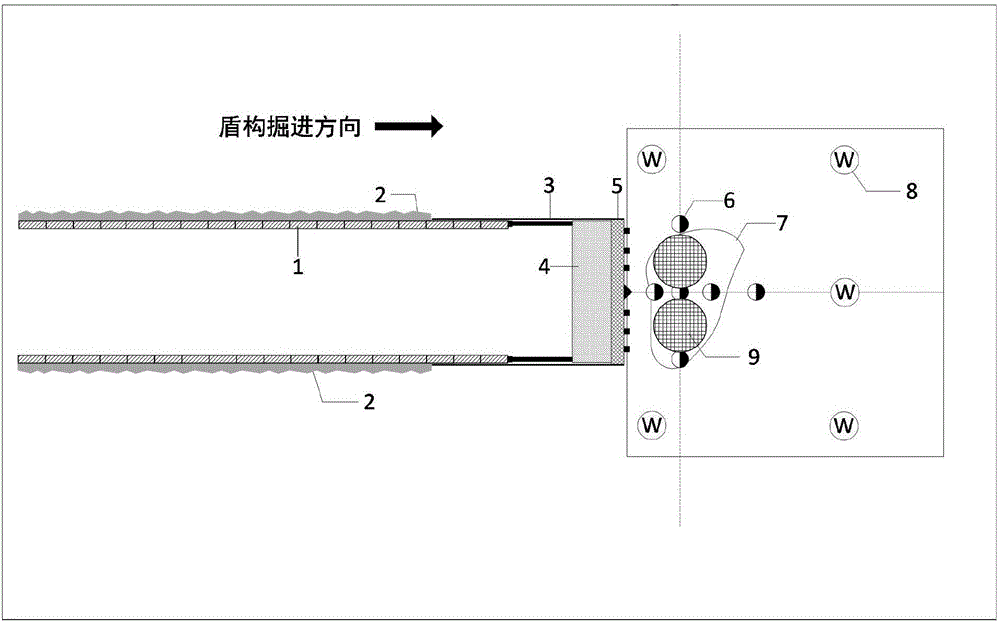
[0036] The shield machine 3 includes a shield machine shell, a shield cutter head 5, an earth ballast chamber 4, a screw conveyor, a propulsion mechanism and a segment structure 2, and the shield machine cutter head 5 is arranged at the front of the shield machine shell. The back of the shield cutterhead 5 is the soil ballast 4, the bottom of the soil ballast 4 is connected with the screw conveyor, and the soil cut by the shield cutterhead 5 enters through the holes distributed on the shield cutterhead 5. In the soil ballast chamber 4, it is transported to the outside of the shield machine casing through the screw conveyor located at the excavation port at the lower part of the soil ballast chamber 4; the shield machine casing is surrounded by propulsion oil cylinders, and the props installed ...


PUM

PropertyMeasurementUnit
Wall thicknessaaaaaaaaaa

Abstract

The invention discloses a sleeve of a full-casing and full-slewing drilling machine. The sleeve of the full-casing and full-slewing drilling machine comprises a sleeve body, wherein the upper end of the sleeve body is connected with the slewing drilling machine; and the lower end of the sleeve body is fixedly connected with a hard alloy serrated knife. The invention further discloses a method for removing barriers in front of a cutter head of a shield tunneling machine. The method comprises the following steps: injecting bentonite in an earth pressure cabin; forming a geological drilling hole, and determining a barrier removing construction affecting range and a burial depth of the barriers in front of the cutter head of the shield tunneling machine by using a drill pipe sticking method; observing change of underground water level; determining the position of the sleeve of the full-casing and full-slewing drilling machine and tunneling to the underground part; cleaning soil bodies and the barriers in the sleeve; forming a sleeve opening in the sleeve by cutting; cleaning the barriers between the sleeve and the cutter head of the shield tunneling machine; and backfilling sandy soil in the sleeve, and gradually pulling up the sleeve in a backfilling process. The sleeve of the full-casing and full-slewing drilling machine has the beneficial effects that the positions and the burial depths of the barriers are determined rapidly, rapid drilling can be realized by the full-casing and full-slewing drilling machine, underground pressure-bearing water level on the periphery is reduced by a dewatering well, piping quicksand risks are avoided, and the opening can be formed in the sleeve to remove the barriers.

Description

technical field [0001] The invention relates to the technical field of shield tunnel construction, in particular to a method for removing obstacles in front of a sleeve of a full-casing full-rotation drilling rig and a shield cutter head. Background technique [0002] During the construction of the shield tunnel, due to the complexity of the engineering geological conditions and the incomplete survey, the shield machine may encounter unknown hard objects such as boulders, boulders or leftover cables and optical cables in front of the shield machine during the construction process, causing the shield tunneling The excavation was difficult and the footage could not be drilled, which made the shield machine in trouble. At present, when such a situation is encountered during shield construction, the strata in front are often reinforced first, and then the type of obstacle in front of the shield cutter head is determined by normal pressure opening. Break through obstacles. Howe...

Claims


Application Information

Patent Timeline
IPC IPC(8): E21D9/08E21D9/12
CPCE21D9/08E21D9/12
Inventor 李忠超蔡兵华杨新罗小东黄超群张耀东谢思俊岚吴丹卢吉肖振
Owner WUHAN MUNICIPAL CONSTR GROUP
Why Eureka
Try Eureka