Liquid vapor floating electric generator

A generator and steam flotation technology, applied in the directions of hydroelectric power generation, engine components, machines/engines, etc., can solve the problems of destroying biological diversity, fragmentation of habitats, and destroying the ecological environment, so as to protect the ecological environment and facilitate adjustment. , the effect of low investment cost

Inactive Publication Date: 2017-05-31
刘德林
View PDF0 Cites 0 Cited by
  • Summary
  • Abstract
  • Description
  • Claims
  • Application Information

AI Technical Summary

Problems solved by technology

[0002] Hydropower generation is to use rivers, lakes, etc. to flow water with potential energy from high places to low places, convert the potential energy contained in it into the kinetic energy of the water turbine, and then use the water turbine as the driving force to drive the generator to generate electricity; in order to effectively use natural water energy, it is necessary Artificial construction of hydraulic structures that can concentrate water drop and regulate flow, such as dams, diversion pipes, etc., not only need to submerge dams in a wide range of upstream areas, but also destroy biodiversity, productive lowlands, forests along river valleys, and wetlands and grasslands, and reservoirs can cause habitat fragmentation in surrounding areas and worsen soil erosion. Therefore, the construction of traditional hydropower stations not only requires large project investment and long construction period, but also seriously damages the ecological environment.

Method used


Image

  • Liquid vapor floating electric generator

Examples


Embodiment Construction

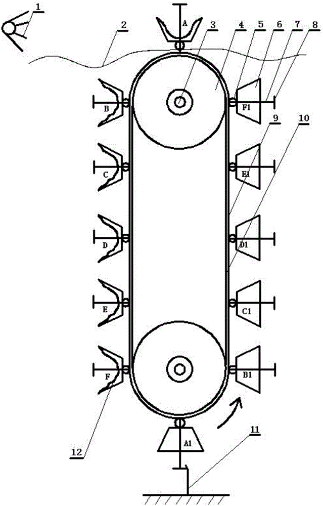
[0009] In the figure, the liquid air flotation generator includes: photocell 1, output power shaft 3, runner 4, photoelectric valve 5, inflatable buoy 6, connecting rod 7, hook 8, crawler air pipe group 9, crawler belt 10, ground Hook 11, airless buoy 12; the liquid vapor flotation generator is installed below the water level, which has a pair of runners 4 connected up and down; the center of the runner 4 is provided with an output power shaft 3, which can drive power generation through the output power shaft 3 The machine does power to generate electricity; a pair of runners 4 are connected and driven through the crawler belt 10; the outer edge of the crawler belt 10 is sequentially provided with a crawler air pipe group 9, and the crawler air pipe group 9 is matched and correspondingly installed with an inflatable buoy 6 and an airless buoy 12; the inflatable buoy 6 There are air pipes corresponding to the airless buoys 12 respectively; a photoelectric valve 5 is installed at...


PUM


Abstract

A liquid vapor floating electric generator is mounted below the horizontal plane and provided with a pair of rotating wheels connected from top to bottom, wherein an output power shaft is arranged at the center of each of the rotating wheels; the output power shafts can drive the electric generator to work to generate electricity; the pair of rotating wheels are in transmission connection through a caterpillar track; a caterpillar track air tube group is arranged on the periphery of the caterpillar track in sequence; inflatable buoys and airless buoys are mounted on the caterpillar track air tube group correspondingly in a matched manner; air tubes are mounted on each of the inflatable buoys and the airless buoys and communicated correspondingly; a photoelectric air valve is mounted at the connection part of each of the buoys and the caterpillar track air tube group; an air valve switch and a hook are mounted on each of the photoelectric air valves; a ground hook is fixedly mounted below the liquid vapor floating electric generator and used for poking the air valve switches. The liquid vapor floating electric generator is simple and compact in structure, convenient and fast to build, applicable to all kinds of hydroelectric power stations, not only low in investment cost, but also short in production cycle and capable of protecting the environment, and moreover has the advantages of high power generation efficiency, low power generation cost, high unit start-up speed and easiness of adjustment.

Description

technical field [0001] The invention relates to a generator, in particular to a liquid vapor floating generator. Background technique [0002] Hydropower generation is to use rivers, lakes, etc. to flow water with potential energy from high places to low places, convert the potential energy contained in it into the kinetic energy of the water turbine, and then use the water turbine as the driving force to drive the generator to generate electricity; in order to effectively use natural water energy, it is necessary Artificial construction of hydraulic structures that can concentrate water drop and regulate flow, such as dams, diversion pipes, etc., not only need to submerge dams in a wide range of upstream areas, but also destroy biodiversity, productive lowlands, forests along river valleys, and wetlands and grasslands, and reservoirs can cause the fragmentation of habitats in surrounding areas and the deterioration of soil erosion. Therefore, the construction of traditional...

Claims


Application Information

Patent Timeline
Patent Type & Authority Applications(China)
IPC IPC(8): F03B17/02F03B9/00
CPCY02E10/20F03B17/02F03B9/00
Inventor 刘德林
Owner 刘德林
Why Eureka
Try Eureka