
Layered regenerative denitration burner

A denitration burner and burner technology, applied in burners, gas fuel burners, combustion methods, etc., can solve the problems of large heat dissipation loss, large area of ​​​​regenerators, and nitrogen dioxide polluting the environment.

Pending Publication Date: 2017-05-31
SHENWU TECH GRP CO LTD
View PDF0 Cites 2 Cited by
  • Summary
  • Abstract
  • Description
  • Claims
  • Application Information

AI Technical Summary

Problems solved by technology

[0004] Regenerative combustion technology, that is, regenerative waste heat recovery technology, the current regenerative waste heat recovery technology, the regenerator is mostly a single straight-through regenerator, and the single regenerator is mostly arranged in a horizontal arrangement, which causes The regenerator occupies a large area, and the high-temperature regenerator is in direct contact with the outside world, resulting in large heat loss
[0005] Therefore, the existing heat storage technology and the problem of nitrogen dioxide pollution in the combustion process need to be solved urgently

Method used


Image

  • Layered regenerative denitration burner

Examples


Embodiment Construction

[0027] Embodiments of the present invention are described in detail below, examples of which are shown in the drawings, wherein the same or similar reference numerals designate the same or similar elements or elements having the same or similar functions throughout. The embodiments described below by referring to the figures are exemplary and are intended to explain the present invention and should not be construed as limiting the present invention.

[0028] In describing the present invention, it is to be understood that the terms "center", "longitudinal", "transverse", "length", "width", "thickness", "upper", "lower", "front", " Back", "Left", "Right", "Vertical", "Horizontal", "Top", "Bottom", "Inner", "Outer", "Clockwise", "Counterclockwise", "Axial" , "radial", "circumferential" and other indicated orientations or positional relationships are based on the orientations or positional relationships shown in the drawings, and are only for the convenience of describing the pre...


PUM


Abstract

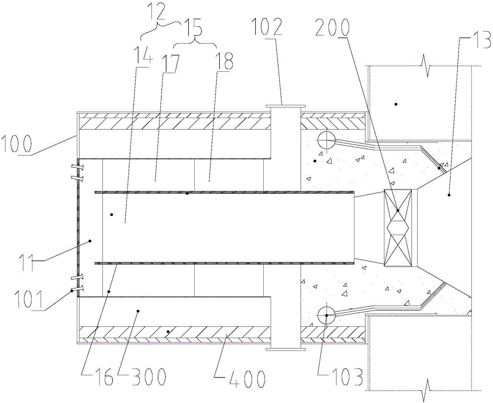
Disclosed is a layered regenerative denitration burner. The layered regenerative denitration burner comprises: a burner body, which includes a gas flow passage, a regenerative chamber and a combustion chamber which are connected in series, wherein the regenerative chamber includes an inner high-temperature regenerative chamber and an outer low-temperature regenerative chamber, the inner high-temperature regenerative chamber communicates with the combustion chamber, the outer low-temperature regenerative chamber encircles at least a part of the outer surface of the inner high-temperature regenerative chamber, partition walls are arranged between the inner high-temperature regenerative chamber and the outer low-temperature regenerative chamber, and the outer low-temperature regenerative chamber comprises a denitration regenerative chamber and a low-temperature regenerative chamber in turn in a direction away from the gas flow passage; a gas flow driving member that is arranged between the inner high-temperature regenerative chamber and the combustion chamber; catalyst inlets disposed on the gas flow passage; openings arranged on the burner body and communicating with the low-temperature regenerative chamber; and gas inlets communicating with the combustion chamber. The usage of the burner can significantly reduce nitrogen oxide emissions in flue gases as well as heat losses.

Description

technical field [0001] The invention belongs to the technical field of gas heat storage and denitrification, in particular, the invention relates to a layered heat storage denitration burner. Background technique [0002] With the rapid development of my country's economy, fossil fuels such as natural gas, oil and coal have been more widely used, making environmental problems increasingly serious, which has caused a series of environmental problems, such as acid rain, ozone layer destruction, greenhouse effect, etc., making us The living environment is becoming more and more severe. my country's coal-based energy structure determines that the emissions of nitrogen oxides and sulfur oxides in our country have always been high. The emission of a large amount of polluting gases has made environmental problems increasingly serious, not only seriously affecting the production and life of our people. , and is not conducive to the sustainable development of my country's economy. Th...

Claims


Application Information

Patent Timeline
Patent Type & Authority Applications(China)
IPC IPC(8): F23D14/22F23D14/66F23D14/46F23J15/02
CPCF23D14/22F23D14/46F23D14/66F23J15/02F23J2215/10Y02E20/34
Inventor 陈珊钟贵全王东方王志军杨玉地吴道洪
Owner SHENWU TECH GRP CO LTD
Learn More