Stress test jig for magnetic material

A magnetic material and stress testing technology, applied in the direction of force/torque/power measuring instruments, measuring devices, instruments, etc., can solve the problems of low work efficiency, high cost, time-consuming and laborious, etc., and achieve reasonable structural design and high work efficiency , the effect of high test accuracy

Inactive Publication Date: 2017-05-31
苏州沃诺斯精密机械有限公司
View PDF6 Cites 2 Cited by
  • Summary
  • Abstract
  • Description
  • Claims
  • Application Information

AI Technical Summary

Problems solved by technology

Therefore, in order to ensure safety during use, the residual internal stress of various magnetic material products is stipulated not to exceed a certain specified value, but the test fixture in the stress testing device of the prior art can only clamp one part at a time, thus As a result, the testing equipment can only perform stress testing on one part at a time, which is time-consuming, labor-intensive, high-cost, and low-efficiency, which cannot meet the requirements of modern industry
Moreover, the flexibility of the test fixture stopper is poor, usually only the stress test in the horizontal direction can be realized, and the test accuracy is low

Method used


Image

  • Stress test jig for magnetic material
  • Stress test jig for magnetic material

Examples


Embodiment Construction

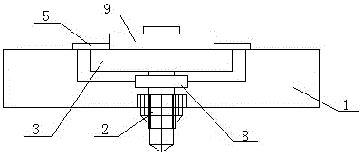
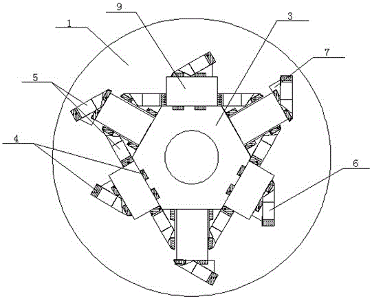
[0016] Such as figure 1 and figure 2 A magnetic material stress test fixture shown includes a test base 1, a test fixture 3 and a plurality of test blocks 5. The middle part of the test base 1 is locked with a pin 2 to install a test fixture 3. The test fixture 3 is a regular polygon. structure, each side of the regular polygon test fixture 3 is provided with at least one test point 4, a plurality of test stoppers 5 are pressed against the magnetic material 9 and fixed on the test fixture 3, and a single test stopper 5 is composed of a trapezoidal block 6 and a triangular block 7 are superimposed, and the two sides of the trapezoidal block 6 and the side of the triangular block 7 are provided with test points 4, and the test fixture 3 and the test points 4 on the test block 4 are connected to the test substrate 1 through the test line.

[0017] In the present embodiment, the opposite surfaces between a plurality of magnetic materials 9 share a test block 5. When the magnetic...


PUM


Abstract

The invention discloses a stress test jig for a magnetic material. The stress test jig comprises a test base body, a test clamp and multiple test stop blocks, wherein the test clamp is mounted at the middle part of the test base body in a locking manner through a pin; at least one test point is arranged on each side of the test clamp; the multiple test stop blocks press against the magnetic material to fix the magnetic material on the test clamp; each test stop block is formed by stacking a trapezoid block and a triangular block, and test points are arranged on two sides of the trapezoid block and the sides of the triangular block; the test points on the test clamp and the test stop blocks are connected with the test base body through test lines. The stress test jig is reasonable in structural design; as the test points are arranged on the test clamp and the test stop blocks, synchronous test in multiple directions can be realized, and the test precision is high; furthermore, tests for multiple magnetic materials can be completed at one time; by distribution of multiple test stop block positions, the stress test jig can adapt to the test work for the the magnetic materials of different specifications, and is high in working efficiency and high in universality.

Description

technical field [0001] The invention relates to the technical field of electronic information materials, in particular to a magnetic material stress testing jig. Background technique [0002] During the casting, welding, forging and mechanical cutting process of magnetic materials, due to the deformation caused by thermal expansion and contraction and mechanical force, residual stress is generated inside the part, which makes the part in an unstable state and reduces the dimensional stability and mechanical physics of the part. Performance, so that the parts will deform and fail due to the release of residual stress during the use of the finished product. Therefore, in order to ensure safety during use, the residual internal stress of various magnetic material products is stipulated not to exceed a certain specified value, but the test fixture in the stress testing device of the prior art can only clamp one part at a time, thus As a result, the testing equipment can only pe...

Claims


Application Information

Patent Timeline
IPC IPC(8): G01L5/00
CPCG01L5/0047
Inventor 钟强
Owner 苏州沃诺斯精密机械有限公司
Why Eureka
Try Eureka