Nadir and limb common optical path integral optical system

An optical system and a common optical path technology, applied in the field of space optics, can solve the problems of incomplete information, difficulty in meeting the requirements of use, singleness, etc., and achieve the effect of solving the single detection mode and improving the accuracy of detection and inversion

Inactive Publication Date: 2017-05-31
CHANGCHUN INST OF OPTICS FINE MECHANICS & PHYSICS CHINESE ACAD OF SCI
View PDF4 Cites 7 Cited by
  • Summary
  • Abstract
  • Description
  • Claims
  • Application Information

AI Technical Summary

Problems solved by technology

[0003] The present invention provides an integrated optical system with a nadir and a limb common optical path in order to solve the problem that the information obta

Method used


Image

  • Nadir and limb common optical path integral optical system
  • Nadir and limb common optical path integral optical system

Examples


specific Embodiment approach 1

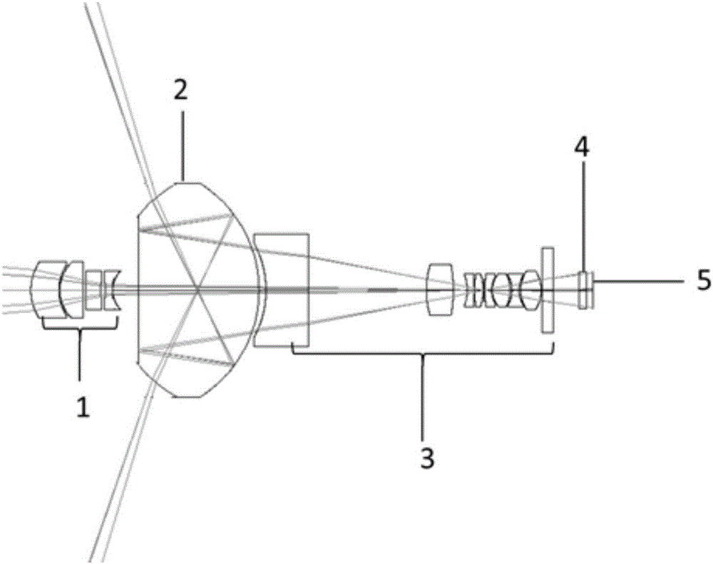
[0013] Specific implementation mode 1. Combination figure 1 Describe this embodiment, the integrated optical system of the nadir and the limb common optical path, including the nadir limb imager, the nadir limb imager includes a front lens group 1, a panoramic ring lens 2, and a relay lens group 3 , a narrowband filter 4 and a CCD detector 5; the central axes of the front lens group 1, the panoramic ring lens 2, the relay lens group 3, the narrowband filter 4 and the CCD detector 5 are on the same straight line.

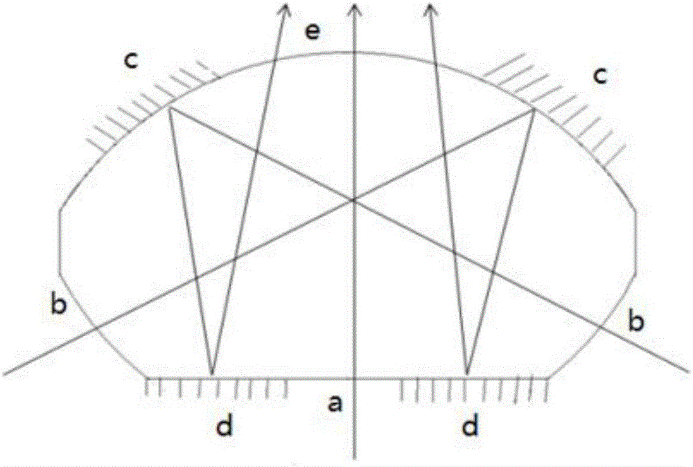
[0014] For the peripheral field of view, the target scene is first formed into a virtual image by the panoramic annular lens 2, and the relay lens group 3 images the virtual image formed by the panoramic annular lens 2 onto the CCD detector 5 with a magnification of -0.5 to 3.

[0015] For the nadir field of view, the target scene is first compressed by the front lens group 1 to compress the beam aperture, and then transmitted into the panoramic annular lens 2 and re...

specific Embodiment approach 2

[0022] Specific implementation mode two, combining figure 1 This implementation mode is described. This implementation mode is an example of the integrated optical system with a nadir and a limb common optical path described in the first specific implementation mode:

[0023] In this embodiment, the nadir-limb imager is a small six-band optical system, which is used to detect the Earth's limb atmosphere at 10° nadir and limb 360° in all directions. The system is expected to work at an orbital height of H= On the 400km satellite platform, the central wavelengths of the six bands are 265nm, 295nm, 360nm, 540nm, 602nm, and 664nm, and the bandwidths are 20nm, 15nm, 6nm, 6nm, 6nm, 6nm, and the center of the six narrowband filters The wavelength corresponds to the bandwidth. The Nadir Limb Panoramic Imager has a nadir field of view of 10°, a limb field of view of 360°×(70.7°~73.5°), and the corresponding Earth limb height ranges from 0 to 100km. The front lens group 1 of the nadir...


PUM

PropertyMeasurementUnit
Bandwidthaaaaaaaaaa

Abstract

The invention discloses a nadir and limb common optical path integral optical system, relates to the technical field of space optics, and aims to solve the problems that detection information is not complete, and use requirements are hard to met as a conventional spatial atmospheric remote sensing detection has single modes. A nadir and limb imager comprises a front lens group, a panorama annular lens, a relay lens group, narrow-band filters and a CCD detector. For a nadir view field, the panorama annular lens is equivalent to a thick lens; the light beam size of a light beam of the nadir view field is firstly reduced through the front lens group, and then the light beam is imaged on the CCD detector through the panorama annular lens and the relay lens group. For a limb view field, light firstly passes through the panorama annular lens to form a virtual image, and the virtual image formed by the panorama annular lens is amplified by the relay lens group and is imaged to the CCD detector. By adopting the nadir and limb common optical path integral optical system, all-direction detection of nadir 10 degrees and limb 360 degrees, and six wave bands are selected by using six narrow-band filters, so that detection information completeness and inversion accuracy of a trace gas can be improved, and the system is applicable to the field of spaceflight atmospheric remote sensing.

Description

technical field [0001] The invention relates to the technical field of space optics, in particular to an optical system integrating a nadir and a limb common optical path. Background technique [0002] Atmospheric remote sensing detection has three detection methods, the nadir detection method, the occultation / lunar detection method and the limb detection method. Among them, the nadir detection method adopts the method of direct downward detection from the zenith, the occultation / lunar detection mode detects the transmitted light in the horizon direction when the sun rises or sets, and the limb detection mode adopts the detection method in the limb height direction. Solar radiation scattered by trace gases. Typical remote sensing instruments using typical nadir detection methods include TOMS, SBUV, GOME, OMI, etc. The remote sensing instruments using the occultation / lunar detection mode include POAMⅡ, SAGEⅢ and so on. There are OSIRIS, SCIAMACHY, and OMPS that use the edg...

Claims


Application Information

Patent Timeline
IPC IPC(8): G01N21/17G01N21/01G02B27/00
CPCG01N21/17G01N21/01G01N2021/0112G01N2021/177G01N2021/178G01N2021/1795G02B27/00
Inventor 薛庆生王晓恒
Owner CHANGCHUN INST OF OPTICS FINE MECHANICS & PHYSICS CHINESE ACAD OF SCI
Why Eureka
Try Eureka