Online monitoring device, detection circuit and testing method for junction temperature of electronic power switch

A technology of power electronic switch and monitoring device, which is applied in the field of power electronics, can solve the problems that have not been properly solved, the voltage dynamic range changes greatly, and it is difficult to accurately measure the millivolt level of the conduction voltage drop, so as to achieve the overall design ingenious, structural Compact and convenient for large-scale promotion and application

Pending Publication Date: 2017-05-31
CHAJNA MAJNING DRAJVS EHND AUTOMEHJSHN KO
View PDF7 Cites 28 Cited by
  • Summary
  • Abstract
  • Description
  • Claims
  • Application Information

AI Technical Summary

Problems solved by technology

The dynamic range of the voltage across the device varies greatly, and it is difficult to accurately measure the change in the millivolt level of the conduction voltage drop caused by the temperature change
Those skilled in the art try new solutions all the time, but this problem has not been properly solved

Method used


Image

  • Online monitoring device, detection circuit and testing method for junction temperature of electronic power switch
  • Online monitoring device, detection circuit and testing method for junction temperature of electronic power switch
  • Online monitoring device, detection circuit and testing method for junction temperature of electronic power switch

Examples


Embodiment 1

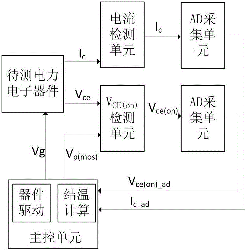
[0026] Embodiment 1: see figure 1 , an online monitoring device for the junction temperature of a power electronic switching device, the online monitoring device includes a main control unit, a power electronic device to be tested, a current detection unit, a V ce(on) A detection unit and an AD acquisition unit, wherein the main control unit includes a device drive unit and a junction temperature calculation unit. In this technical solution, the power electronic switching device to be tested includes common power electronic switching devices, including MOSFETs, IGBTs, etc.; the current detection unit is used for Acquisition of the current I flowing through the device in the on state of the device c , V ce(on) The detection unit is used to collect the conduction voltage drop V of a certain rated time period in the IGBT conduction state ce , through V ce(on) The analog circuit in the detection unit obtains the equivalent conduction voltage drop signal V ce(on , the AD acqui...

Embodiment 2

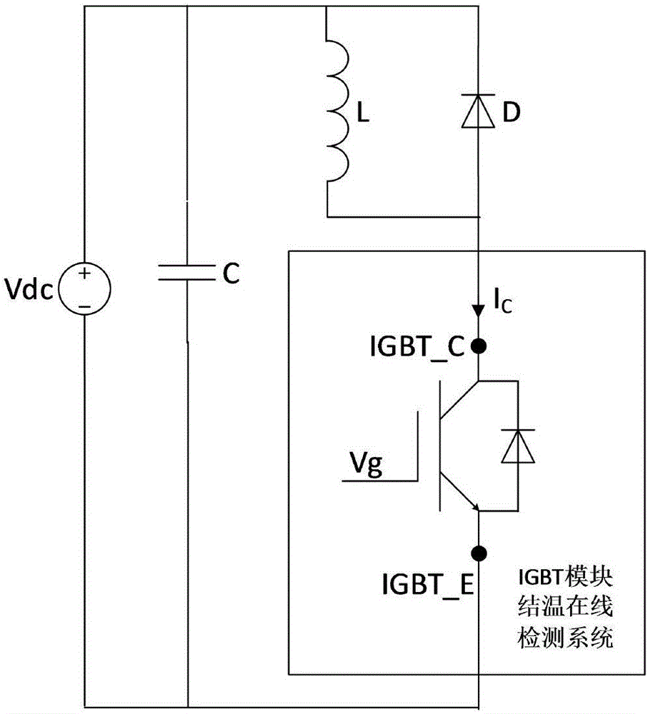
[0029] Example 2: see figure 2 , an IGBT detection circuit provided with an online junction temperature monitoring device of a power electronic switching device, wherein the detection circuit includes a bus DC voltage source Vdc, a bus capacitor C, a load inductance L, a power diode D, and an IGBT module junction temperature online detection system; wherein , the positive pole of the bus DC voltage source Vdc is connected to one end of the bus capacitor C, one end of the load inductance L to the cathode of the power diode D, and the other end of the load inductance is connected to the anode of the power diode D and the collector of the IGBT module to be tested in the IGBT module junction temperature online detection system IGBT_C is connected, and the emitter IGBT_E of the IGBT module to be tested in the IGBT module junction temperature online detection system is connected to the other end of the bus capacitor and the negative pole of the bus DC voltage source Vdc.

Embodiment 3

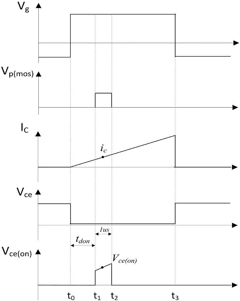
[0030] Embodiment 3: see image 3 , the test steps of the IGBT module junction temperature detection device using the IGBT module detection circuit are as follows: image 3 The timing diagram of IGBT drive and mos drive shown in the figure cooperates to complete the measurement of high-precision conduction voltage drop, at t 0 -t 3 During the time period, the switching control signal V of the gate of the IGBT module g is high level, the IGBT module to be tested is in the conduction state, and the switch control signal V of the gate of the IGBT module is in the rest of the time g is low level, the IGBT module to be tested is in the off state; at t 1 -t 2 During the time period, V ce(on) Q1 in the sense cell turns on, making V ce(on) The detection unit is connected to the IGBT module junction temperature online detection system, and the rest of the time V ce(on) Q1 in the detection cell turns off, so that V ce(on) The detection unit is disconnected from the IGBT module jun...


PUM


Abstract

The invention relates to an online monitoring device, a detection circuit and a testing method for a junction temperature of an electronic power switch. The online monitoring device comprises a master control unit, a to-be-tested power electronic device, a current detection unit, a Vce(on) detection unit and an AD collection unit, wherein the master control unit comprises a device driving unit and a junction temperature calculation unit power electronic switch device, the current detection unit is used for collecting a current Ic flowing through the device in a conducting state; the Vce(on) detection unit is used for collecting a conducting pressure drop Vce of an IGBT in a certain rated time period in a conducting state and obtaining an equivalent conducting pressure drop signal Vce(on) by virtue of an analogue circuit in the Vce(on) detection unit; the AD collection unit is used for finishing the conversion from simulation current and voltage to digital signals; the device driving unit is used for providing a gate electrode driving signal Vg of a to-be-tested device and a switch signal Vp(mos) of the Vce(on) detection unit; and an IGBT driving unit is used for regulating a level fluctuation sequential relationship between a gate electrode switch control signal Vg of an IGBT module and the switch signal Vp(mos) of the Vce(on) detection unit in the IGBT driving unit.

Description

technical field [0001] The invention relates to a monitoring device, in particular to an on-line monitoring device for junction temperature of a power electronic switching device, belonging to the technical field of power electronics. Background technique [0002] With the development of the power electronics technology industry, power electronic devices, as the core devices of energy conversion and transmission, are more and more widely used. When the power converter system is running, the temperature of the chip will rise due to the switching loss and conduction loss of the device, which will cause the internal material of the device to bear thermal stress, accelerate the aging degree and failure rate of the switching device, and cause the converter to fail. [0003] Estimation of the junction temperature of switching devices is of great significance to its reliability, health status and lifetime evaluation. Accurate measurement of device junction temperature is an urgent...

Claims


Application Information

Patent Timeline
Patent Type & Authority Applications(China)
IPC IPC(8): G01R31/26
CPCG01R31/2617G01R31/2619
Inventor 谭国俊耿程飞李浩张经纬王凯吴义可
Owner CHAJNA MAJNING DRAJVS EHND AUTOMEHJSHN KO
Why Eureka
Try Eureka