
Focusing lens and vibrating mirror type laser scanning system

A lens and focusing technology, applied in the field of optical engineering, can solve the problems such as the scanning range should not be too large, the error increases, the optical design and focusing model are complicated, etc., to achieve the effect of small adjustment error and simple structure

Active Publication Date: 2017-05-31
SHENZHEN INST OF ADVANCED TECH
View PDF7 Cites 4 Cited by
  • Summary
  • Abstract
  • Description
  • Claims
  • Application Information

AI Technical Summary

Problems solved by technology

[0005] The galvanometer rear focusing method adopts the traditional F-theta lens focusing method. Due to the limitation of the lens size, the scanning range should not be too large, and the beam focusing characteristics at the edge of the scanning surface have become very poor.
[0006] The optical design and focusing model of the laser scanning system in the front focusing mode of the galvanometer are relatively complicated
Too many lenses will increase the errors caused by processing and assembly, which will affect the focusing effect
In addition, this type of 3D scanning system basically has a real focus point in the optical path in addition to the scanning surface. The focus point of the high-energy laser beam will cause excessive temperature and increase the risk of equipment damage

Method used


Image

  • Focusing lens and vibrating mirror type laser scanning system
  • Focusing lens and vibrating mirror type laser scanning system
  • Focusing lens and vibrating mirror type laser scanning system

Examples


Embodiment Construction

[0028] In order to enable those skilled in the art to better understand the technical solutions in the present invention, the technical solutions in the embodiments of the present invention will be clearly and completely described below in conjunction with the drawings in the embodiments of the present invention. Obviously, the described The embodiments are only some of the embodiments of the present invention, not all of them. Based on the embodiments of the present invention, all other embodiments obtained by persons of ordinary skill in the art without creative efforts shall fall within the protection scope of the present invention.

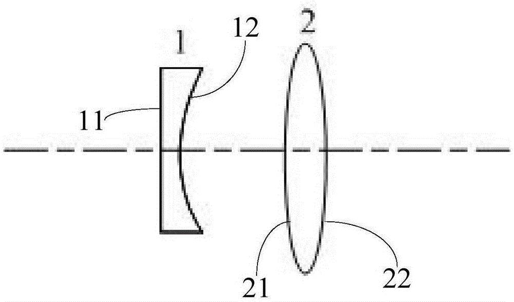
[0029] The invention discloses a dual-mirror dynamic focusing lens, which aims to optimize the existing dynamic focusing module optical system. The structure of the focusing lens is simpler, and the focusing lens has no real focus so that the structure is not easy to generate high temperature.

[0030] Specifically, see figure 1 As shown, the...


PUM

PropertyMeasurementUnit
Radiusaaaaaaaaaa

Abstract

The invention discloses a focusing lens and a vibrating mirror type laser scanning system. The focusing lens comprises a flat concave lens and a convex lens, the flat concave lens comprises a plane and a concave surface arranged opposite to the plane, and the convex lens which is arranged fixedly comprises a first convex surface and a second convex surface arranged opposite to the plane; the flat concave lens can move in the axis, and light is input via the plane of the flat concave lens, passes the concave surface of the flat concave lens and the first convex surface of the convex lens successively, and is output via the second convex surface of the convex lens. The focusing lens is simple in structure and low in the adjusting error; the focusing lens has no real focus and thus, can be kept in a relatively low temperature; and when the waist radius of an input laser beam of the vibrating mirror type laser scanning system is greater than 7.5mm, the distance between a laser and the focusing lens does not influence the focusing effect.

Description

technical field [0001] The invention relates to the technical field of optical engineering, in particular to a focusing lens and a galvanometer laser scanning system. Background technique [0002] Laser scanning technology is a technology that can precisely control the pointing of laser beams. It has been widely used in optoelectronic medical treatment, laser processing, space laser communication, laser radar, remote sensing and measurement, adaptive optics and other fields. In the field of laser processing and laser compliance, galvanometer laser scanning technology has been used. In order to ensure the accuracy of laser processing, the laser needs to be focused before reaching the processing surface to ensure good focusing characteristics on the working surface. According to the position of the focusing system, it can be divided into two types of focusing: the front focus of the galvanometer and the focus after the galvanometer. Way. [0003] Patent CN101419336B in the p...

Claims


Application Information

Patent Timeline
IPC IPC(8): G02B26/10
CPCG02B26/0875G02B26/128
Inventor 陈巍陈四海徐越罗栋张骁苏凯斌
Owner SHENZHEN INST OF ADVANCED TECH
Learn More