Refueling water tank inside containment of nuclear power plant

A nuclear power plant containment and water tank technology, applied in nuclear power generation, nuclear engineering, cooling devices, etc., can solve problems that affect equipment reliability and layout convenience, raise the height of the main circuit equipment layout, and increase the overall height of the reactor building, etc. Achieve the effect of ensuring water quality stability and reliability, improving reliability and convenience of layout, and improving mixing effect

Active Publication Date: 2018-04-27
中广核工程有限公司 +1
View PDF3 Cites 0 Cited by
  • Summary
  • Abstract
  • Description
  • Claims
  • Application Information

AI Technical Summary

Problems solved by technology

[0006] 1) The area at the bottom of the pool is limited by the structure of the secondary shielding wall, and the water depth is relatively large, which increases the overall height of the reactor building, raises the layout height of the main circuit equipment, and affects the overall earthquake resistance of the building;
[0007] 2) The internal layout space is limited and the equipment layout is compact, which is not conducive to pool mixing;
[0008] 3) The water depth of the pool is large, and it is not conducive to ensuring the NPSH of the pump when the water is taken at a low water level;
[0009] 4) The retention basket needs to filter the debris in the main equipment area, annular space area and other areas. A single piece of equipment has a large load of debris, which affects the reliability of the equipment and the convenience of layout

Method used


Image

  • Refueling water tank inside containment of nuclear power plant
  • Refueling water tank inside containment of nuclear power plant
  • Refueling water tank inside containment of nuclear power plant

Examples


Embodiment Construction

[0033] In order to make the purpose, technical solution and technical effect of the present invention clearer, the present invention will be further described in detail below in conjunction with the accompanying drawings and specific embodiments. It should be understood that the specific implementations described in this specification are only for explaining the present invention, not for limiting the present invention.

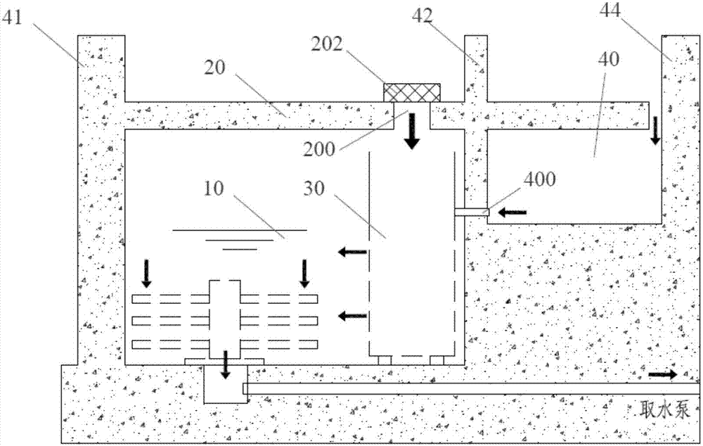
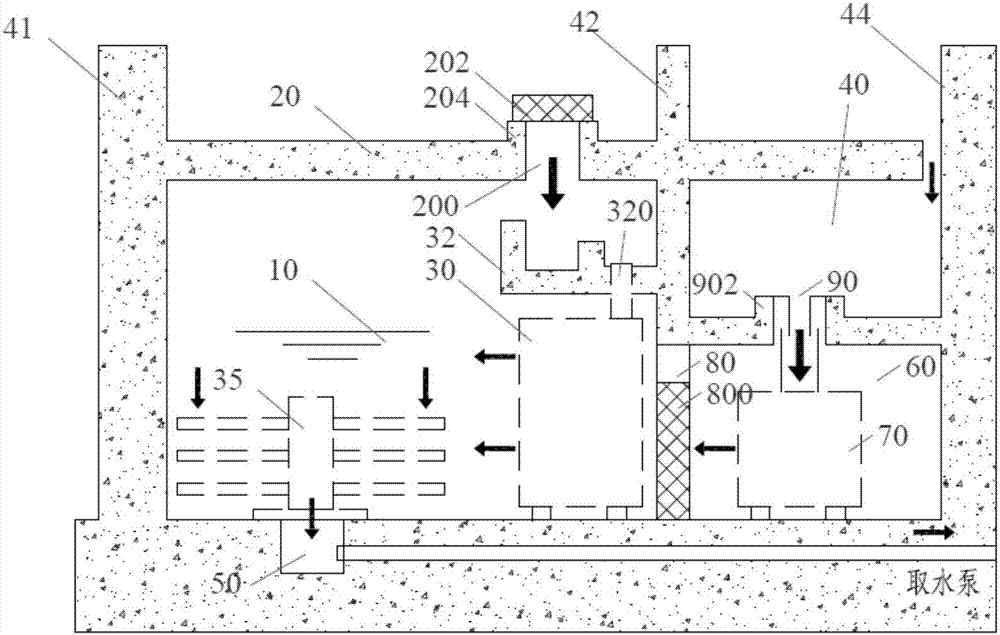
[0034] see figure 2 As shown, the refueling water tank inside the nuclear power plant containment of the present invention includes: an inner ring pool 10 located between the nuclear power plant reactor pit 41 and the secondary shielding wall 42 and a load-bearing floor 20 above the inner ring pool 10, the load-bearing floor 20 is provided with The inner ring water return hole 200, the inner ring water pool 10 is provided with an inner ring retention basket 30 corresponding to the inner ring water return hole 200, and an inner ring backflow buffer pool is pr...


PUM


Abstract

The invention discloses an in-containment refueling water storage tank for a nuclear power station. The refueling water tank comprises an inner ring pool located between a reactor pit of the nuclear power station and a secondary shielding wall, and a bearing floor located at the upper part of the inner ring pool, wherein an inner ring water return hole is formed in the bearing floor; an inner ring detaining basket corresponding to the inner ring water return hole is arranged in the inner ring pool; an inner ring reflux buffer pool is arranged between the inner ring water return hole and the inner ring detaining basket; an annular space is formed between the secondary shielding wall and the containment vessel of the nuclear power station; an outer ring pool is arranged at the lower part of the floor of the annular space; the outer ring pool is communicated with the annular space through an outer ring water return hole; an outer ring detaining basket corresponding to the outer ring water return hole is arranged in the outer ring pool; and the outer ring pool is communicated with the inner ring pool through a channel. Compared with the prior art, the in-containment refueling water storage tank has the advantages that the outer ring pool is arranged in the refueling water tank with the built-in containment vessel for the nuclear power station, so that the volume of the refueling water tank with the built-in containment vessel can be significantly improved; the water depth is reduced and the shock resistance of a reactor building is improved.

Description

technical field [0001] The invention belongs to the field of nuclear power engineering, and more specifically, the invention relates to a refueling water tank inside a containment vessel of a nuclear power plant. Background technique [0002] With the development of economy and society and the increasing requirements for environmental protection, nuclear power technology, as one of the clean energy technologies, is also constantly developing. At present, the world's major nuclear power technology suppliers are developing third-generation nuclear power technology to improve the safety of nuclear power plants. As a part of the safety system of nuclear power plants, the in-containment refueling water tank (IRWST) has become the development trend of the third-generation nuclear power technology in the world. [0003] In the third-generation nuclear power technology with built-in refueling water tank in the active containment, the refueling water tank is arranged at the bottom o...

Claims


Application Information

Patent Timeline
Patent Type & Authority Patents(China)
IPC IPC(8): G21C13/02G21C15/18
CPCG21C13/02G21C15/18Y02E30/30
Inventor 彭国胜周媛霞程浩王庆礼丁楠韩浪
Owner 中广核工程有限公司
Why Eureka
Try Eureka