
A composite mov component with discharge structure

A composite and component technology, applied in the direction of varistors, varistor cores, resistance terminals/electrodes, etc., can solve problems such as hindering the application field and affecting the service life of MOV, and achieve easy processing and great economic use value , no leakage current effect

Active Publication Date: 2019-05-17
LONGKE ELECTRONICS HUIYANG
View PDF8 Cites 3 Cited by
  • Summary
  • Abstract
  • Description
  • Claims
  • Application Information

AI Technical Summary

Problems solved by technology

[0003] With the rapid development of clean energy technology, the popularization of high-speed rail and the wide application of electronic machinery (such as robots, manipulators, etc.), the leakage current generated by the charging of existing MOVs hinders some application fields and affects the use of MOVs. Longevity, such as railway track signals; these areas must be protected, and leakage current is not allowed during normal operation, such as 5G communications. Due to the performance requirements of high reliability and long life disposable products, the existing MOV cannot meet the actual need for further improvement

Method used


Image

  • A composite mov component with discharge structure
  • A composite mov component with discharge structure
  • A composite mov component with discharge structure

Examples


Embodiment 1

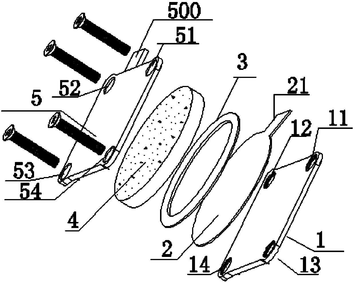
[0031] Such as figure 1 As shown, the present invention provides a composite MOV assembly with a discharge structure, that is, an FDMOV assembly, including an insulating fixed plate 1, a discharge electrode sheet 2, an insulating ring sheet 3, an MOV chip 4, a tripping electrode 5 and a fastener, The MOV chip 4 is a circular MOV chip 4 .

[0032] The insulating fixing plate 1 is a rectangular insulating fixing plate, and four screw holes 11 , 12 , 13 , 14 are provided at the four corners of the rectangular insulating fixing plate.

[0033] Described discharge electrode sheet 2 is circular discharge electrode sheet, and the straight edge of described circular discharge electrode sheet is identical with described circular MOV chip, and described discharge electrode sheet 2 is also provided with lead-out electrode 21.

[0034] The insulating ring sheet 3 is an annular insulating ring sheet, and the profile of the annular insulating ring sheet is 1-5mm larger than the diameter of...

Embodiment 2

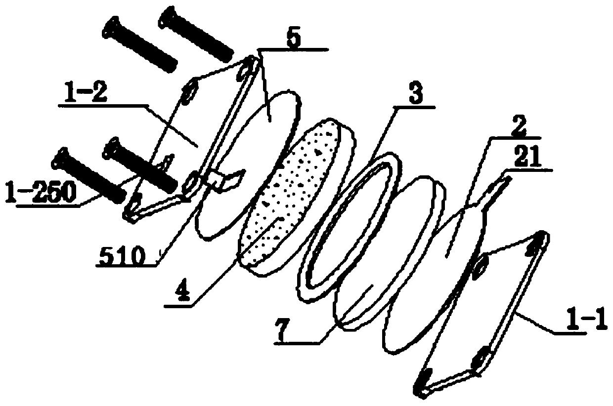
[0042] Such as figure 2 As shown, the difference between this embodiment and Embodiment 1 is that it includes a discharge electrode 7, and the discharge electrode 7 is arranged between the discharge electrode sheet 2 and the insulating ring sheet 3, and the insulating fixing plate includes a second An insulating fixing plate 1-1 and a second insulating fixing plate 1-2, the second insulating fixing plate 1-2 is arranged above the tripping electrode 5, and the second insulating fixing plate 1-2 is provided with a groove Holes 1-250 and fasteners;

[0043]A discharge electrode 7 is added between the discharge electrode sheet 2 and the insulating ring sheet 3, the discharge electrode sheet 2 is used as a lead-out electrode, the tripping electrode 5 is a circular tripping electrode, and the circular tripping electrode 5 is a circular tripping electrode. The diameter of the electrode is the same as the diameter of the MOV chip, and the circular trip electrode is provided with a l...

Embodiment 3

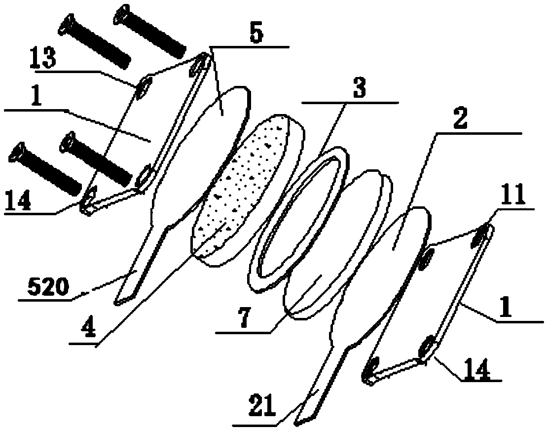
[0046] The difference between this embodiment and Embodiment 1 and Embodiment 2 is that the lead-out pin 520 of the tripping electrode 5 is set to lead out in a radial direction and extended so that the FDMOV with air discharge can be used in a PCB circuit board components.

[0047] Such as Figure 4 Shown are the equivalent circuit diagrams of Embodiment 1, Embodiment 2, and Embodiment 3 of the present invention.


PUM


Abstract

The invention provides a complex type MOV (Metal Oxide Varistor) assembly with a discharging structure, i.e., an FDMOV assembly. The assembly comprises an insulating fixing plate, a tripping electrode, a discharging electrode, an insulating ring sheet and an MOV chip, wherein the discharging electrode, the insulating ring sheet and the MOV chip are sequentially sandwiched between the insulating fixing plate and the tripping electrode; the insulating fixing plate and the tripping electrode are fixed through fasteners. The assembly does not withstand operating voltage during use and has the characteristics of no current leakage, long life, high reliability, convenience in processing and reduced cost; heated welding is not required after all components and parts are subjected to cold working, so that thermal damage is avoided, and the mounting is simple and rapid; the assembly is suitable for being mechanized, and the cost is low, so that the assembly has a great economic use value.

Description

technical field [0001] The present invention relates to the technical field of metal oxide varistors, in particular to a composite MOV assembly with a discharge structure, hereinafter referred to as FDMOV assembly. Background technique [0002] The existing zinc oxide varistors (Metal Oxide Varistors, MOV) have special nonlinear current-voltage characteristics. When the application environment encounters lightning strikes, electromagnetic field interference, frequent power switch actions, and power system failures, the voltage on the line will be reduced. Sudden increase, exceeding the conduction voltage of the MOV, makes the MOV enter the conduction region, and the current and voltage have a nonlinear relationship. At this time, the impedance of the MOV becomes low, only a few ohms, causing the overvoltage to form a sudden Wave current flows out to protect connected electronic products or expensive components. [0003] With the rapid development of clean energy technology,...

Claims


Application Information

Patent Timeline
Patent Type & Authority Patents(China)
IPC IPC(8): H01C7/112H01C1/14H01C1/01
CPCH01C1/01H01C1/14H01C7/112
Inventor 陈泽同曾清隆
Owner LONGKE ELECTRONICS HUIYANG
Learn More