LRC component structure

A component structure and component technology, which is used in electrical components, electrical solid devices, semiconductor devices, etc., to reduce mechanical stress, simplify component structure, and save installation area.

Inactive Publication Date: 2017-05-31
BEIJING YUANLIU HONGYUAN ELECTRONICS TECH
View PDF4 Cites 0 Cited by
  • Summary
  • Abstract
  • Description
  • Claims
  • Application Information

AI Technical Summary

Problems solved by technology

In addition, due to the ceramic composition of chip ceramic components, the product is brittle and susceptible to adverse stresses such as mechanical stress and thermal stress.

Method used


Image

  • LRC component structure
  • LRC component structure
  • LRC component structure

Examples


Embodiment 1

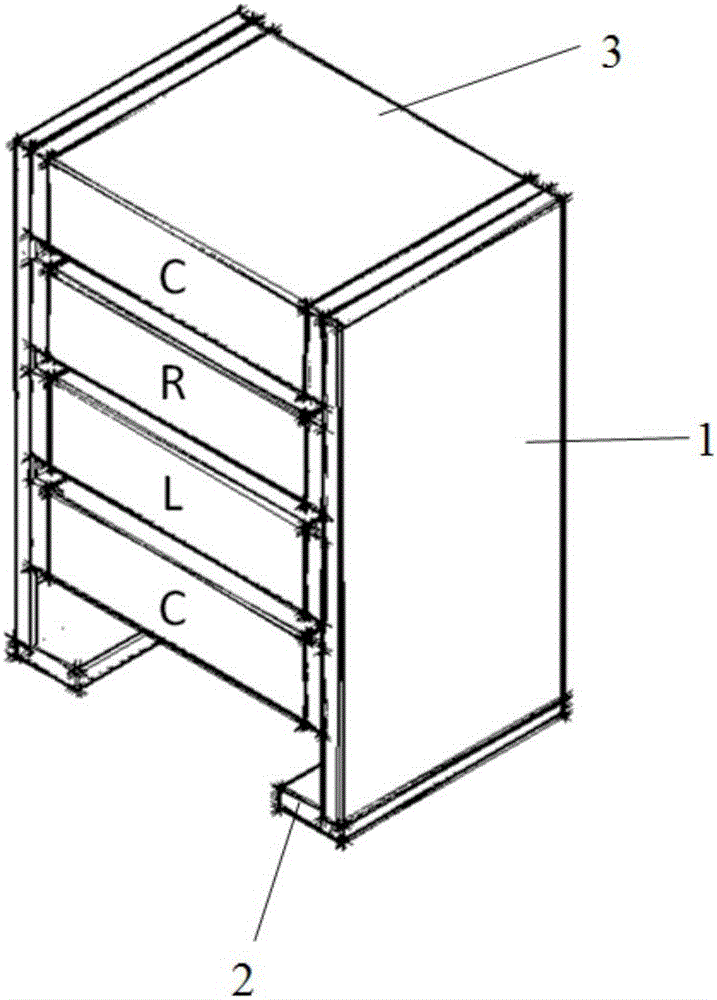
[0021] Realize the parallel LRC resonant tank M1, the structure is as follows figure 1 As shown, it includes: two pole plate supports 1, at the lower ends of the two pole plate supports 1 there are pins 2 inclined inwardly or outwardly, and the pins are fixedly connected with the circuit board. The multi-piece RC-sensing elements 3 are welded on the inner side of the two pole plate supports 1, the multi-piece RC-sensing elements 3 are connected in series or in parallel, and the multi-piece RC-sensing elements 3 are stacked vertically or arranged horizontally.

[0022] The LRC component structure is done in the following steps:

[0023] 1. Processing and treatment of pole plate support: process the required metal pole plate by machining, and then perform electroplating treatment to form an electroplating layer on the surface of the pole plate support.

[0024] 2. Chip bonding: According to the principle of the circuit diagram, the size and parameters of the resistance-capacita...

Embodiment 2

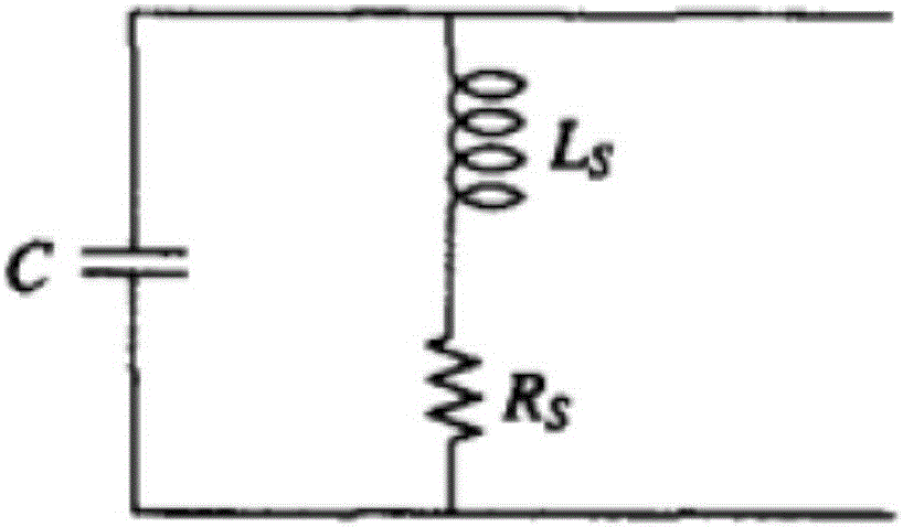
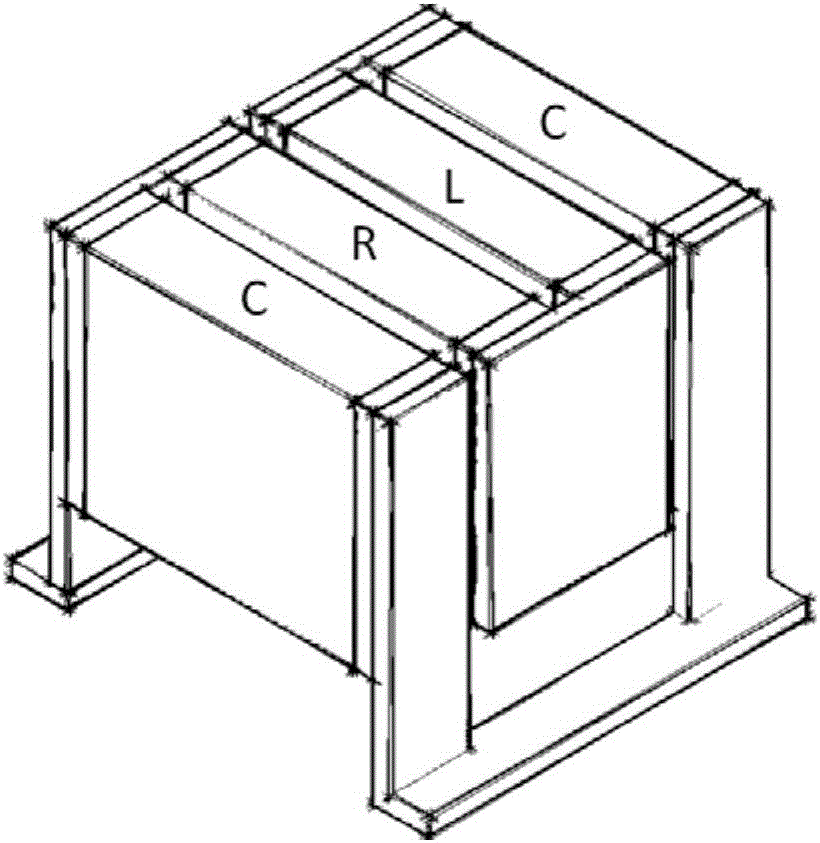
[0029] Series-parallel LRC resonance circuit M2, the circuit schematic diagram is as follows figure 2 Shown, the modular component structure designed by the method of the present invention is as image 3 As shown, the series connection of L and R and the parallel connection with C can be realized, and the corresponding pins can be soldered according to the needs during use.

Embodiment 3

[0031] A π-type low-pass filter (LPF) M3, the circuit schematic diagram is as follows Figure 4 As shown, for modular replacement, the LRC component structure is as follows Figure 5 shown.


PUM


Abstract

The invention relates to the technical field of a component structure and particularly relates to a LRC component structure. The LRC component structure comprises the steps that: two metal support electrode plates are arranged on the element end electrode for electric connecting and fixing and buffering roles; two electrode plate supports are provided with a derivation pin derived inward or outward in the bottom; the derivation pin is fixedly connected to a circuit board; multichip LRC elements which are in series connection or parallel connection are soldered inside the two electrode plate supports. The multichip resistance capacitance element is vertical stack installation or horizontal stack installation. According to the corresponding principle or function of circuit, corresponding pins are only soldered on a bonding pad at using time, the LRC element bodies not touch the bonding pad, the impacts made by undesirable stress such as mechanical stress, temperature stress and the like are reduced by the buffer function of the electrode plate supports, the reliability for the LRC components is increased. The elements installation occupancy area is effectively saved through the stack component modular structure, and the line distribution parameter is reduced at the same time.

Description

technical field [0001] The invention relates to the technical field of component structures, in particular to an LRC component structure. Background technique [0002] Chip RC sensor is a common passive component, which has the characteristics of small size, good resistance to heat and humidity, and high cost performance. At present, it has been widely used in computers, various electronic equipment, aerospace and other fields, and has become an indispensable part of electronic equipment. In electronic circuits, capacitors, resistors, and inductors (LRC) are used in series and parallel. According to different combinations, they can be designed into products such as low-pass filters and high-pass filters or realize functions such as resonant circuits and LRC networks. . [0003] Usually when we use SMD LRC components in practice, we first design PCB, ceramic substrate and other circuit boards according to the circuit schematic diagram, then solder the resistance-capacitance...

Claims


Application Information

Patent Timeline
Patent Type & Authority Applications(China)
IPC IPC(8): H01L27/01H01L23/495
CPCH01L27/01H01L23/495H01L23/49534H01L23/49589
Inventor 刘晓龙李凯吴胜琴
Owner BEIJING YUANLIU HONGYUAN ELECTRONICS TECH
Why Eureka
Try Eureka