A Frequency Tunable Microstrip Patch Antenna

A microstrip patch antenna and frequency technology, which is applied to antennas, resonant antennas, and devices that make antennas work in different bands at the same time, can solve problems such as affecting progress, offset, and errors, and achieve the effect of widening the antenna bandwidth

Inactive Publication Date: 2019-05-14
UNIV OF ELECTRONICS SCI & TECH OF CHINA
View PDF3 Cites 0 Cited by
  • Summary
  • Abstract
  • Description
  • Claims
  • Application Information

AI Technical Summary

Problems solved by technology

However, it also has practical application defects, the most important of which is that there will be certain errors between the processed physical test results and the theoretical results of the software simulation; the reason for these errors is: the design of the microstrip antenna is to use the plate as the radiation unit, Usually, due to the processing and production of the plates we actually use, the production of different batches of the same model will lead to changes in the dielectric constant, loss tangent, thickness, etc. of the plates themselves, and we set these indicators of the plates during software simulation They are all set according to the ideal situation, which leads to a certain error between the processed physical test results and the theoretical results of the software simulation.
Among these errors, the most deadly is the frequency offset. The size of the frequency is related to the length and width of the patch on the dielectric board. The frequency offset is divided into high and low. According to microwave theory, if it is low , then it is only necessary to reduce the size. At this time, the length and width of the microstrip antenna can be cut in equal proportions by physical methods, and the frequency of the antenna can be changed to high frequencies; but if the processed antenna frequency is too high, In order to reduce the frequency, we need to increase the size, and the length of the processed antenna patch has been processed according to the simulated size, which cannot be increased. This will directly affect the actual engineering process and require redesign and processing, causing great harm to actual research and application. troubled

Method used


Image

  • A Frequency Tunable Microstrip Patch Antenna
  • A Frequency Tunable Microstrip Patch Antenna
  • A Frequency Tunable Microstrip Patch Antenna

Examples


Embodiment Construction

[0017] The present invention will be further described below in conjunction with the accompanying drawings and embodiments.

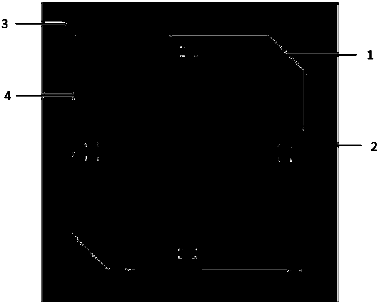
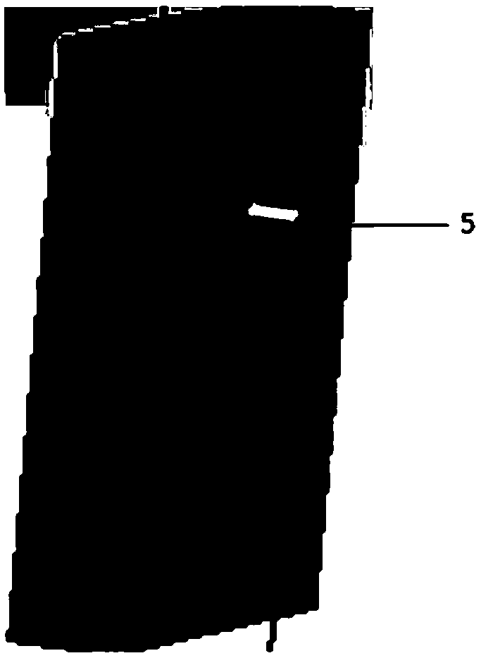
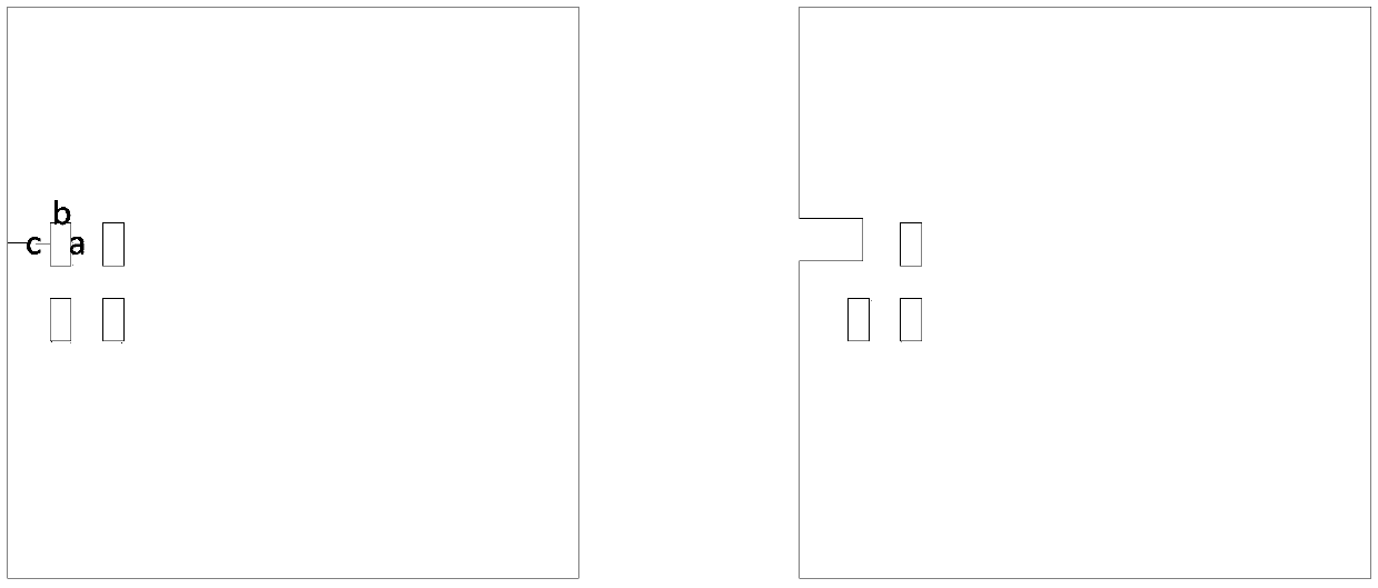
[0018] This embodiment provides a frequency-tunable microstrip patch antenna, the structure of which is as follows figure 1 , 2 As shown, it includes a radiation patch 1, a dielectric plate 3, a feed port 4, and an excitation source port 5. The radiation patch 1 is arranged on the upper surface of the dielectric plate 3, and the excitation source port 5 is connected to the feed port 4 for Excitation, characterized in that an even number of patch holes 2 of the same size are symmetrically arranged on the opposite side of the radiation patch 1, the patch holes 2 are arranged in an array, and the center of the array is located on the midline of the corresponding opposite side , each patch hole is rectangular.

[0019] Wherein, the radiating patch 1 and the small holes of the patch are all made by printed circuit technology; the dielectric plate 3 is made...


PUM


Abstract

The invention belongs to the field of microwave devices, and in particular relates to a frequency-adjustable microstrip patch antenna, comprising a radiation patch, a dielectric plate, a feeding port and an excitation source port, wherein the radiation patch is arranged on the upper surface of the dielectric plate, and the The excitation source port is connected to the feeding port for excitation, and an even number of patch holes of the same size are symmetrically arranged on the opposite sides of the radiation patch, the patch holes are arranged in an array, and the center of the array is located on the corresponding opposite side On the midline of , each patch hole is rectangular. The invention can widen the bandwidth of the antenna by opening the patch holes on the radiation patch, and at the same time, when the processed microstrip patch antenna has a frequency offset after testing, the radiation patch can be conveniently cut along the patch holes. , which effectively corrects the frequency offset of the microstrip patch antenna.

Description

technical field [0001] The invention belongs to the field of microwave devices, in particular to a frequency-tunable microstrip patch antenna. Background technique [0002] With the development of science and technology, the miniaturization of devices has become the most important technical point in practical research and application. The microstrip antenna can work at 100MHz-100GHz. The advantages of using a dielectric plate as a radiation unit and simple design make it widely used in modern microwave transceivers. The system field is an indispensable part of today's microwave devices. Microstrip antennas have the following advantages: 1. Small size, light weight, low profile, and conformal to carriers such as aircraft and mobile communication terminals; 2. Low manufacturing cost, easy to mass produce, and linear polarization and Circular polarization; 3, small scattering cross-section, easy to make dual-frequency, dual-polarized antennas; 4, can be easily integrated with ...

Claims


Application Information

Patent Timeline
Patent Type & Authority Patents(China)
IPC IPC(8): H01Q9/04H01Q1/36H01Q5/30
CPCH01Q1/36H01Q5/30H01Q9/0407
Inventor 杨青慧赵志晨张怀武文岐业刘元昆
Owner UNIV OF ELECTRONICS SCI & TECH OF CHINA
Why Eureka
Try Eureka