A temperature control method for a power distribution cabinet

A technology for power distribution cabinets and power distribution rooms, which is applied in temperature control, non-electric variable control, substation/power distribution device shells, etc. It can solve the problems of affecting heat dissipation effect, waste of space cost, and short service life of electrical components, etc., to achieve Good heat dissipation effect, improve the safety of use, and prolong the service life

Active Publication Date: 2019-05-03
珠海盈源电气有限公司
View PDF4 Cites 0 Cited by
  • Summary
  • Abstract
  • Description
  • Claims
  • Application Information

AI Technical Summary

Problems solved by technology

[0002] The power distribution cabinet is a commonly used power equipment. It is used to install electrical components. The electrical components will generate heat when they are in use. Therefore, a fan is usually installed on the power distribution cabinet. The fan is generally located on the side of the power distribution cabinet. The windshield, the fan position draws air outside, and the windshield enters the wind, thereby reducing the temperature inside the power distribution cabinet. However, in this way, the contact surface between the circulating air and the electrical components is small, which affects the heat dissipation effect. The problem of short service life
[0003] On the other hand, the temperature in the power distribution cabinet should not be too low, because the air temperature is low, its ability to be saturated with water will become poor, and condensation will easily form on the surface of electrical components. The impact of water on the electrical system is destructive. The loss caused by the short circuit is difficult to estimate
For this reason, a heating type dehumidifier is also installed in the power distribution cabinet. The heating type dehumidifier is mainly realized by increasing the temperature in the power distribution cabinet. Since the air with a higher temperature can contain more moisture, it prevents water vapor from directly entering the cabinet. Condensation on electrical equipment, terminal blocks, etc. in the cabinet prevents accidents such as flashovers and short circuits; however, setting a heating dehumidifier in a cabinet is a waste of space and cost, and after all, the power distribution cabinet needs to dissipate heat. Lord, the less heating the better

Method used


Image

  • A temperature control method for a power distribution cabinet
  • A temperature control method for a power distribution cabinet
  • A temperature control method for a power distribution cabinet

Examples


Embodiment 1

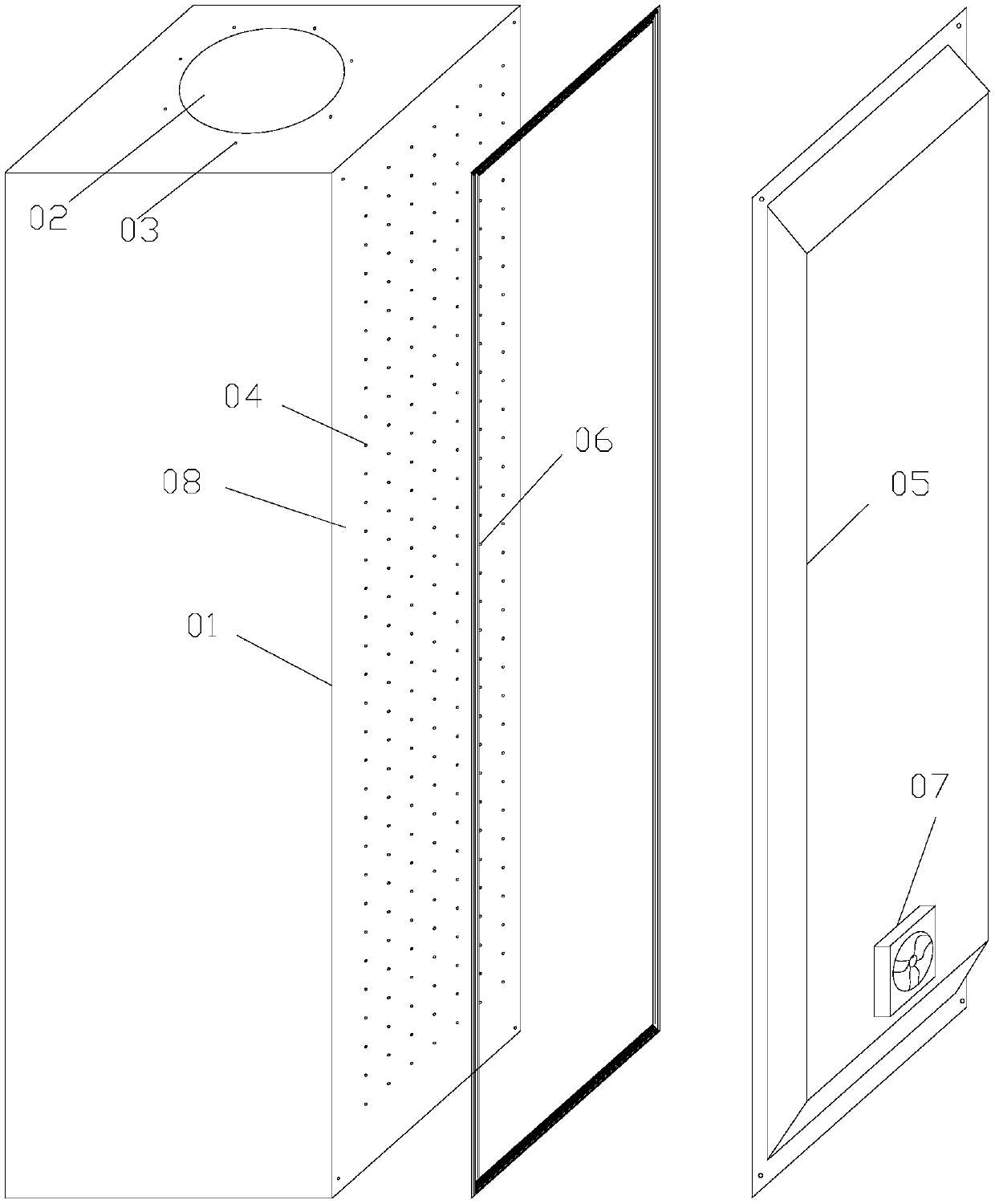
[0037] Such as figure 1 As shown, the power distribution cabinet described in this embodiment, the power distribution cabinet, includes a cabinet body 01, which is characterized in that the top of the cabinet body 01 is provided with a ventilation hole 02, and a circle of first installation holes 03 is provided on the periphery of the ventilation hole 02 ; The backboard 08 of the cabinet body 01 is covered with screw holes 04, and a back chamber 05 is connected to the back of the cabinet body 01, and a frame-type sealing strip 06 is provided between the backboard 08 and the back chamber 05; A fan 07 is provided at the bottom of the back cavity 05 .

[0038] The beneficial effect of the power distribution cabinet described in this embodiment is that the backboard 08 is covered with screw holes 04, and components such as bus ducts and clips for installing electrical components are directly installed on the backboard through screws. 07 When turning to the internal air supply, th...

Embodiment 2

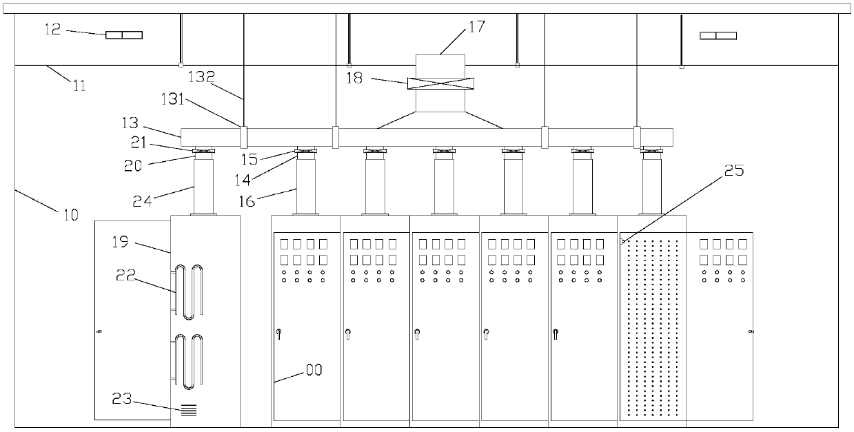
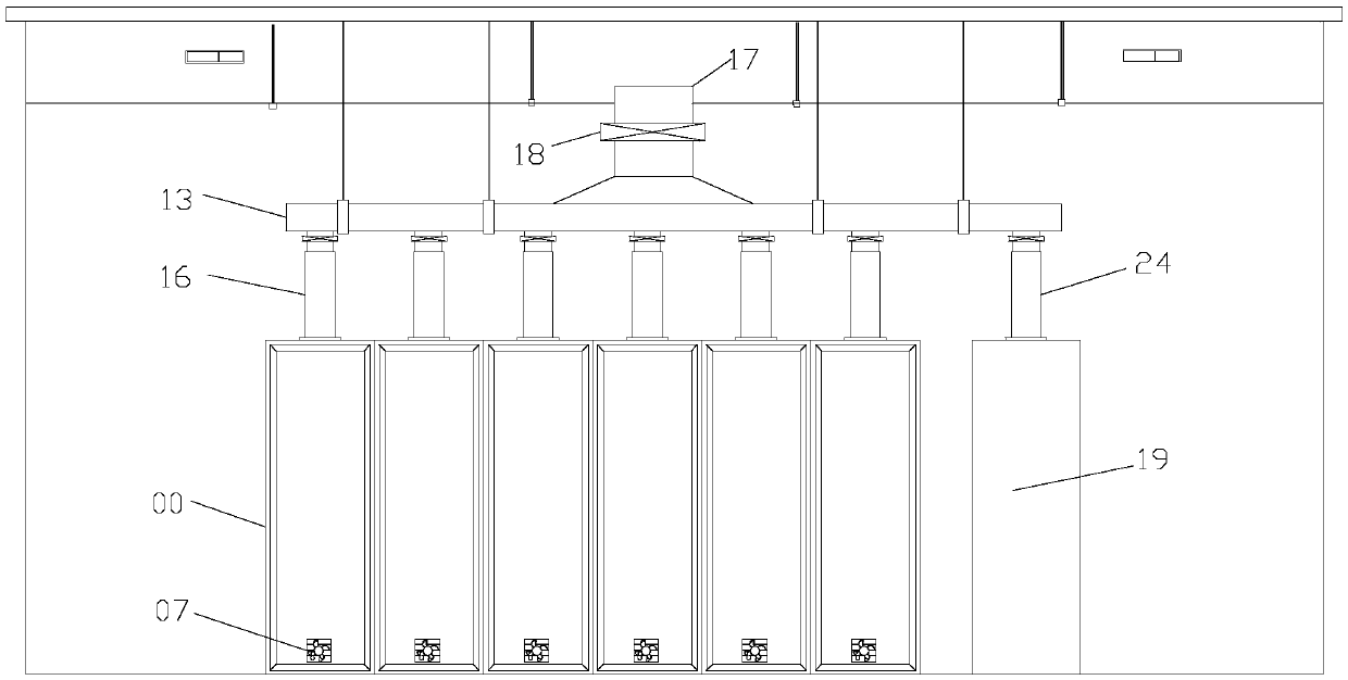
[0040] Such as figure 2 , 3 As shown, the temperature control system of the power distribution cabinet described in this embodiment includes several power distribution cabinets 00 as described in Embodiment 1 located in the power distribution room 10, the upper part of the power distribution room 10 is provided with a suspended ceiling 11, A ventilation window 12 is provided above the suspended ceiling 11; an air duct 13 is provided above the power distribution cabinet 00, and the bottom surface of the air duct 13 is provided with the same number of air outlets 14 as the power distribution cabinet 00, and the air outlet 14 is provided with ventilation Valve 15, a ventilation pipe 16 is connected between the air outlet 14 and the ventilation hole 02 of the corresponding power distribution cabinet 00; the top of the air duct 13 is provided with an exhaust pipe 17, and the outlet of the exhaust pipe 17 is located above the suspended ceiling 11 and in the row The air pipe 17 is ...


PUM


Abstract

The invention discloses a power distribution cabinet. The power distribution cabinet comprises a cabinet body, wherein a ventilation hole is formed in the top of the cabinet body, and one circle of first mounting holes are formed in the periphery of the ventilation hole; dense screw holes are formed in a backing plate of the cabinet body, the back of the cabinet body is connected with a back cavity, and a frame type sealing strip is arranged between the backing plate and the back cavity; and a fan is arranged at the lower part of the back cavity. According to the power distribution cabinet disclosed by the invention, airflow is blown out from the back cavity and the screw holes in the backing plate when the fan rotates forwards and supplies the air inwards, and the blown-out wind is directly blown onto electrical components, so that the airflow can be pushed toward the ventilation hole in the top to be blown out, and heat dissipation effect is better. The invention also discloses a temperature control system and a temperature control method of the power distribution cabinet, when the temperature of the power distribution cabinet is lower than TA, the power distribution cabinet at higher temperature can carry out temperature compensation on the power distribution cabinet at low temperature through an air duct for preventing condensation, so that the temperature of the power distribution cabinet at the low temperature rises; and the temperature in the power distribution cabinet can be better controlled, so that the power distribution cabinet can meet temperature demand during operation, the use safety is improved, and the service lives of the electrical components are prolonged.

Description

technical field [0001] The invention relates to electric equipment, in particular to a power distribution cabinet and a temperature control system and method for the power distribution cabinet. Background technique [0002] The power distribution cabinet is a commonly used power equipment. It is used to install electrical components. The electrical components will generate heat when they are in use. Therefore, a fan is usually installed on the power distribution cabinet. The fan is generally located on the side of the power distribution cabinet. The windshield, the fan position draws air outside, and the windshield enters the wind, thereby reducing the temperature inside the power distribution cabinet. However, in this way, the contact surface between the circulating air and the electrical components is small, which affects the heat dissipation effect. The problem of short service life. [0003] On the other hand, the temperature in the power distribution cabinet should not...

Claims


Application Information

Patent Timeline
Patent Type & Authority Patents(China)
IPC IPC(8): H02B1/56H02B1/28G05D23/20
CPCG05D23/20H02B1/28H02B1/565
Inventor 高明
Owner 珠海盈源电气有限公司
Why Eureka
Try Eureka