Ammonia spraying grating device

An ammonia injection grille and the same technology are applied in the field of environmental protection industrial flue gas treatment technology and equipment, which can solve problems such as unsatisfactory mixing effect, limited mixing uniformity, and reduced denitration efficiency, so as to improve the distribution of ammonia concentration field and improve mixing. effect, effect

Pending Publication Date: 2017-06-13
BEIJING CPCEP ENERGY CONSERVATION & ENVIRONMENTAL PROTECTION TECH CO LTD
View PDF5 Cites 7 Cited by
  • Summary
  • Abstract
  • Description
  • Claims
  • Application Information

AI Technical Summary

Problems solved by technology

The ammonia injection grid is arranged in the flue, and the nozzles in the ammonia injection grid inject ammonia gas. Under the action of the catalyst, the injected ammonia (NH 3 ) and nitrogen oxides (NO X ) mixing and reacting, the mixing degree of the two determines the denitrification efficiency, if the flue gas and ammonia gas are not mixed enough, the denitrification efficiency will decrease and the ammonia escape will increase, resulting in serious secondary pollution
[0003] The structure of the traditional ammonia injection grid is to directly arrange the spray holes on the ammonia injection main pipe or to protrude the equal diameter (that is, non-gradient) ammonia injection branch pipes. ideal
When the flue length is not enough, the mixing uniformity of ammonia gas and flue gas is limited, which affects the denitrification efficiency

Method used


Image

  • Ammonia spraying grating device
  • Ammonia spraying grating device
  • Ammonia spraying grating device

Examples


Embodiment Construction

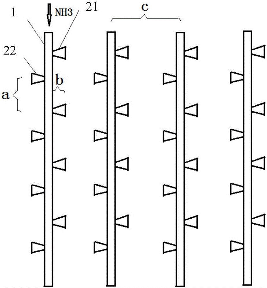
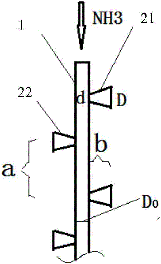
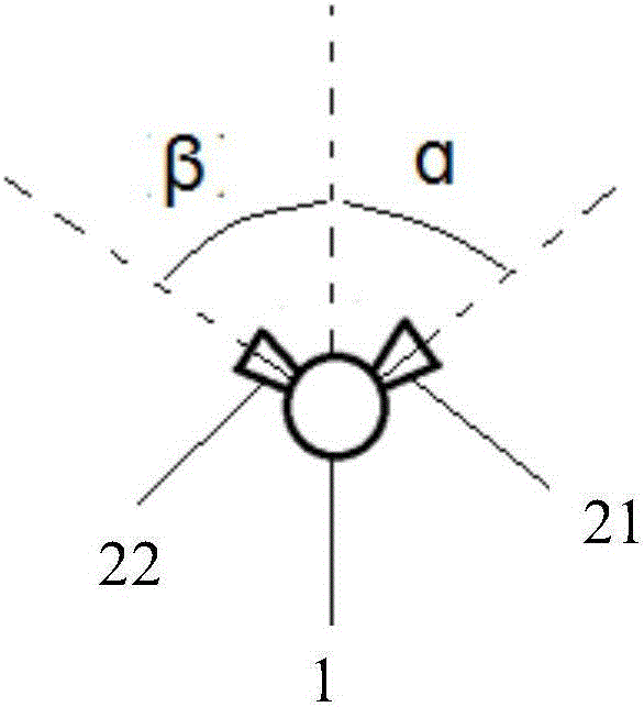
[0022] In order to better understand the purpose, structure and function of the present invention, an ammonia injection grill device of the present invention will be further described in detail below in conjunction with the accompanying drawings.

[0023] Such as Figure 1 to Figure 3 As shown, it is shown as an ammonia injection grid device of the present invention, comprising a plurality of ammonia injection master pipes 1, and a plurality of ammonia injection master pipes 1 are arranged side by side in the same section perpendicular to the flue gas flow direction; the ammonia injection master pipes 1 is provided with a plurality of ammonia injection branch pipes, which are connected with the ammonia injection main pipe 1. The ammonia injection main pipe 1 is provided with a plurality of injection holes, and the ammonia injection branch pipes are vertically inserted into the ammonia injection main pipe through the injection holes respectively. The ammonia injection main pipe...


PUM

PropertyMeasurementUnit
diameteraaaaaaaaaa
lengthaaaaaaaaaa
pore sizeaaaaaaaaaa

Abstract

The invention discloses an ammonia spraying grating device, which comprises multiple ammonia spraying main pipes (1) and multiple ammonia spraying branch pipes, wherein the multiple ammonia spraying main pipes (1) are arranged in parallel in the same section perpendicular to the flow direction of a flue gas; the multiple ammonia spraying branch pipes are communicated with the ammonia spraying main pipes (1); the ammonia spraying main pipes (1) are provided by multiple jet holes; the ammonia spraying branch pipes are perpendicularly inserted into the ammonia spraying main pipes respectively through the jet holes; an ammonia gas is diffused and sprayed out from the ammonia spraying main pipes through the ammonia spraying branch pipes to be mixed with the flue gas. The ammonia spraying grating device provided by the invention can be used for effectively promoting the diffusion mixing between the ammonia gas and the flue gas, ameliorating the distribution of the concentration field of the ammonia gas and improving reaction efficiency; the mixed ammonia gas is sprayed out from the ammonia spraying main pipes through the ammonia spraying branch pipes; the effect that the mixed ammonia gas is subjected to diffusion through the ammonia spraying branch pipes is obvious; the sprayed out ammonia gas can be sufficiently mixed with the flue gas through a short distance; the concentration distribution of the ammonia gas is quite uniform.

Description

technical field [0001] The invention relates to the field of environmental protection industrial flue gas treatment technology equipment, in particular to an ammonia injection grid device used in the flue of a denitrification and desulfurization system. Background technique [0002] In the current flue gas treatment system, the most commonly used flue gas denitrification technology is selective catalytic reduction (SCR). The injection and mixing of ammonia gas is one of the core process technologies, and the flue gas treatment technology is the most The central device is the ammonia injection grid (AIG). The ammonia injection grid is arranged in the flue, and the nozzles in the ammonia injection grid inject ammonia gas. Under the action of the catalyst, the injected ammonia (NH 3 ) and nitrogen oxides (NO X ) mixing reaction, the mixing degree of the two determines the denitrification efficiency. If the flue gas and ammonia gas are not mixed enough, the denitrification eff...

Claims


Application Information

Patent Timeline
Patent Type & Authority Applications(China)
IPC IPC(8): B01D53/90B01D53/56
CPCB01D53/8631B01D53/90B01D2251/2062B01D2258/0283
Inventor 韩玉维江浩单选户白云峰初炜马志刚纳宏波郭少鹏刘洋陈雪姜圆王德俊刘亚周文伟王巧真
Owner BEIJING CPCEP ENERGY CONSERVATION & ENVIRONMENTAL PROTECTION TECH CO LTD
Why Eureka
Try Eureka