Exhaust gas in-cylinder direct injection turbulent combustion system and method

A technology of combustion system and exhaust gas cylinder, which is applied in the direction of charging system, exhaust gas recirculation, machine/engine, etc., can solve the problems of reducing intake air volume, potential risk of soot emission, and decrease of excess air coefficient, so as to prevent local The effect of over-rich mixture, promotion of fuel diffusion mixing, and suppression of NOx formation

Active Publication Date: 2021-01-19
WEICHAI HEAVY MACHINERY CO LTD
View PDF10 Cites 0 Cited by
  • Summary
  • Abstract
  • Description
  • Claims
  • Application Information

AI Technical Summary

Problems solved by technology

However, the exhaust gas recirculation intake port injection will occupy part of the intake air, and the exhaust gas temperature is usually high, forming a certain heating effect on the intake air, resulting in a decrease in intake air performance, which will affect the power output of the engine and cause a decrease in power performance
In addition, there is a large amount of non-combustible gas in the exhaust gas, which causes the combustion speed to slow down, the combustion volume to decrease, and the thermal efficiency to decrease.
Although this technical solution can reduce NOx emissions to a large extent, due to the reduction of intake air volume and the decrease of excess air coefficient, there is a potential risk to soot emissions, which can lead to increased soot emissions

Method used


Image

  • Exhaust gas in-cylinder direct injection turbulent combustion system and method
  • Exhaust gas in-cylinder direct injection turbulent combustion system and method
  • Exhaust gas in-cylinder direct injection turbulent combustion system and method

Examples


Embodiment 1

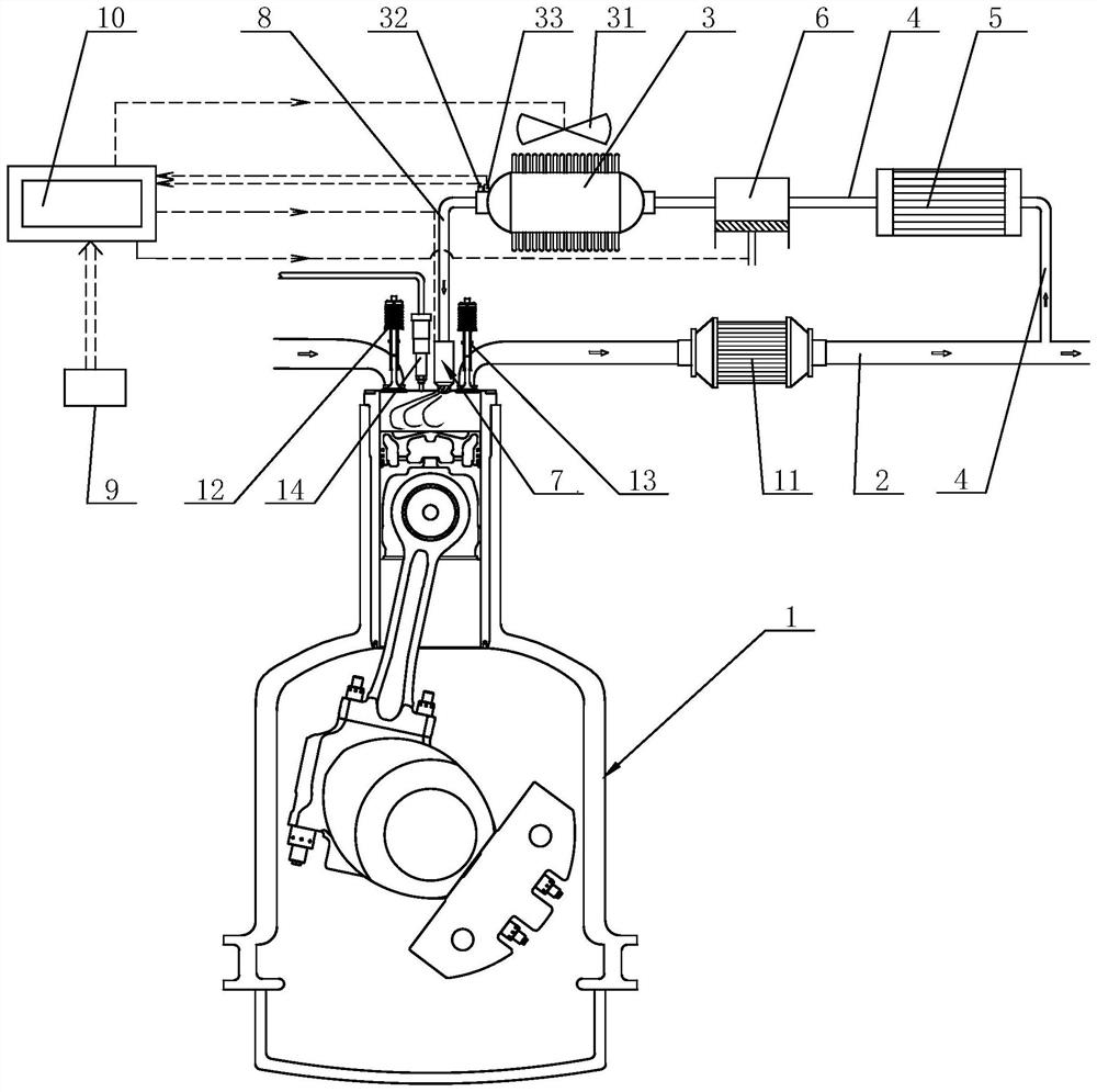
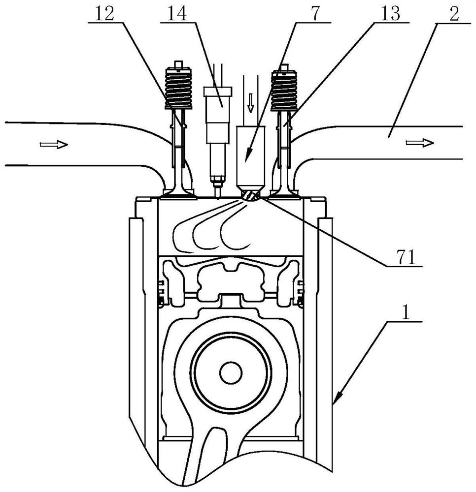
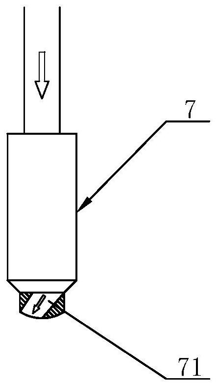
[0034] Such as figure 1 , figure 2 with image 3 Commonly shown, a waste gas in-cylinder direct injection turbulent combustion system includes a cylinder 1 and an exhaust pipe 2 communicating with the cylinder 1. The gas tank 3 communicates with the exhaust pipe 2 through the waste gas introduction pipe 4. The gas tank 3 is provided with Cooling system 31, the exhaust gas introduction pipe 4 is provided with an intercooler 5 and a compressor 6 in sequence along the exhaust gas flow direction; the exhaust gas injector 7 communicates with the gas tank 3 through the exhaust gas injection pipe 8, and the exhaust gas injector 7 is installed on the cylinder of the cylinder 1 Cover, the exhaust gas injector 7 injects exhaust gas into the cylinder 1 at a certain angle; the working condition detection unit 9 is used to detect the engine working condition, and output signals to the electronic control unit 10 (engine ECU); the electronic control unit 10 is used to detect the engine wor...

Embodiment 2

[0048] This embodiment is basically the same as Embodiment 1, the difference is that, as Figure 4 with Figure 5 Commonly shown, the outlet of the exhaust gas injector 7 is not provided with a guide channel 71, and the cylinder head of the cylinder 1 is provided with a guide channel 15 at the exhaust gas injector 7, and a guide channel 15 is provided between the guide channel 15 and the center line of the cylinder 1. There are angles.

[0049] To sum up, the waste gas in-cylinder direct injection turbulent combustion system and method provided by the embodiments of the present invention simultaneously reduce NOx and soot emissions without causing a decrease in engine power and economic performance; Optimal power, economy and emissions performance.


PUM


Abstract

The invention discloses a waste gas cylinder inner direct injection turbulent combustion system and method and belongs to the technical field of engine tail gas treatment. The system comprises a gas cylinder, an exhausting pipe, a gas tank, a waste gas injector and a working condition detection unit. The gas tank communicates with the exhausting pipe through a waste gas introducing pipe. The gas tank is provided with a cooling system. The waste gas introducing pipe is provided with an intercooler and a gas compressor. The waste gas injector communicates with the gas tank through a waste gas injection pipe. The waste gas injector is installed on a cylinder cover of the air cylinder. An electronic control unit judges the working condition of an engine according to the output signal of the working condition detection unit, sends a waste gas injection instruction to the waste gas injector during the compression stroke, and controls the waste gas injection phase and the injection amount, and the waste gas is injected into a combustion chamber of the air cylinder through the waste gas injector at a certain angle, so that strong turbulence is formed. The system can reduce emission of NOxand soot at the same time, and power output and economic performance of the engine will not be influenced.

Description

technical field [0001] The invention belongs to the technical field of engine tail gas treatment, and in particular relates to a waste gas in-cylinder direct injection turbulent combustion system and method. Background technique [0002] At present, international and domestic ship emission regulations are becoming increasingly stringent. The International Maritime Organization (IMO) requires ships built after 2016 to meet Tier III emission requirements, while the domestic side requires the full implementation of China's inland river second-stage emission regulations in July 2021. Faced with the huge pressure to reduce emissions, various marine internal combustion engine manufacturers have intensified the research and development of clean internal combustion engines, and proposed the use of Miller cycle, exhaust gas recirculation (EGR, Exhaust Gas Recirculation), water spray in cylinder, SCR (Selective Catalytic Reduction, selective catalytic reduction method), two-stage supe...

Claims


Application Information

Patent Timeline
Patent Type & Authority Patents(China)
IPC IPC(8): F02M26/01F02M26/22
CPCF02M26/01F02M26/22F02M2026/001
Inventor 唐志刚刘琨然李东润张波高明春任明广
Owner WEICHAI HEAVY MACHINERY CO LTD
Why Eureka
Try Eureka