Long-span prefabricated slab structure

A large-span, prefabricated component technology, applied in the direction of floor slabs, building components, building structures, etc., can solve the problems of complex construction, large impact on construction period, and thick floor slabs, so as to overcome long construction time, reduce construction time, and improve construction efficiency fast effect

Pending Publication Date: 2017-06-13
浙江华恒建筑设计有限公司
View PDF8 Cites 0 Cited by
  • Summary
  • Abstract
  • Description
  • Claims
  • Application Information

AI Technical Summary

Problems solved by technology

It can be seen that the construction of the laminated slab is still relatively cumbersome, and because of the erection of the prefabricated component support frame and the pouring of the laminated floor, it takes up a lot of construction time. In addition, the upper laminated slab needs to be erected on the lower laminated slab. Synchronous construction cannot be achieved between the upper and lower floors, and the support frame needs to wait for the cast-in-place concrete layer of the lower laminated slab to reach a certain strength before erection. It can be seen that the current structural form of the laminated slab and its construction technology have a relatively small impact on the construction period. Big
[0005] In addition, for large-span concrete structures, such as multi-storey parking lots, large-bay office and teaching buildings, the span of the floor slab is relatively large, resulting in a relatively large thickness of the corresponding floor slab, or the need to set more secondary beams. It is not very economical, and when there are many secondary beams, it will have a great impact on the layout of pipelines on the floor ceiling

Method used


Image

  • Long-span prefabricated slab structure
  • Long-span prefabricated slab structure
  • Long-span prefabricated slab structure

Examples


Embodiment Construction

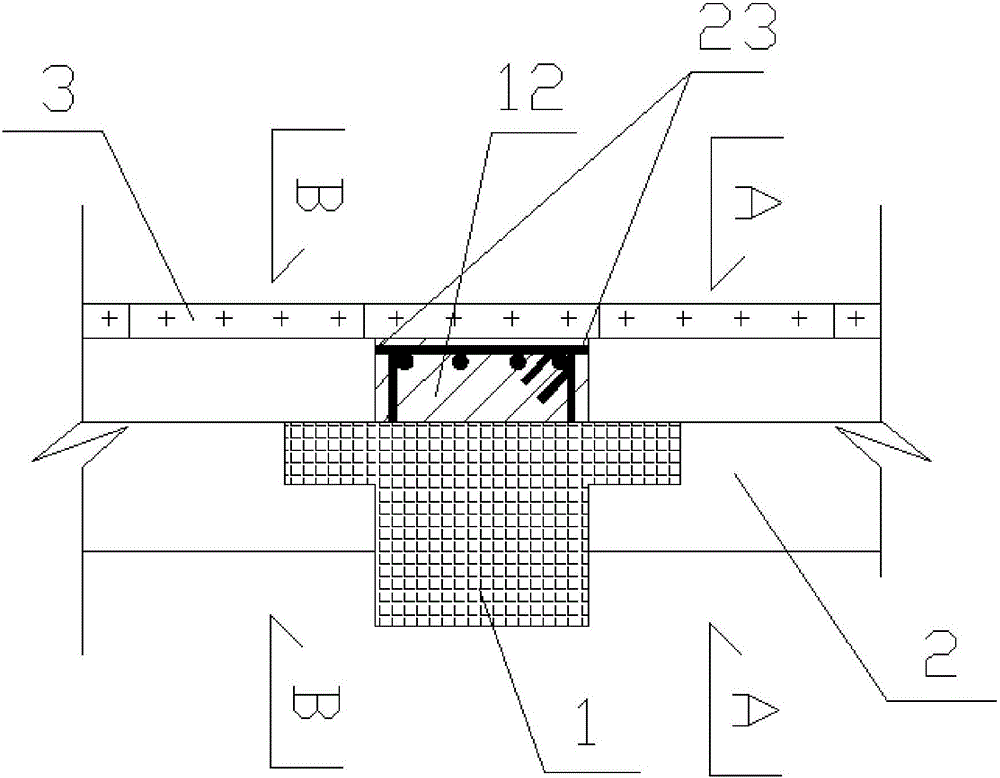
[0031] Please refer to the attached figure 1 To attach Figure 8 As shown, the present invention is a long-span prefabricated floor structure, which is composed of several parts such as a superimposed T-shaped main beam 1 and a T-shaped beam slab 2 .

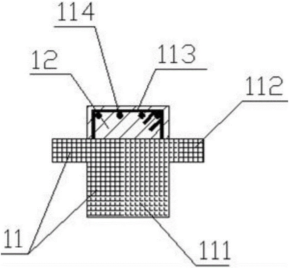
[0032] Wherein, the laminated T-shaped main girder 1 is composed of a T-shaped beam prefabricated component 11 and a laminated layer 12; 112, exposed stirrups 113, main girder upper reinforcement 114 form.

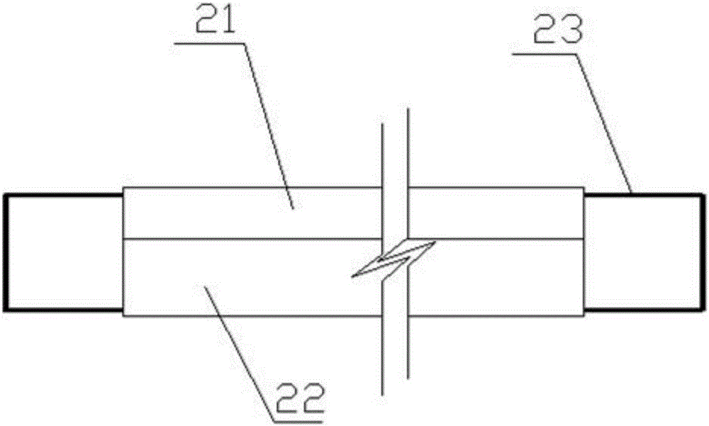
[0033] The T-shaped beam plates 2 are placed side by side and parallel on the lugs 112 of the laminated T-shaped main beam 11 . The T-shaped beam plate 2 is composed of a concrete flange plate 21, a concrete trapezoidal beam 22, and exposed steel bars 23 of the trapezoidal beam. Wherein, the exposed steel bar 23 of the trapezoidal beam protrudes from both ends of the concrete trapezoidal beam 22 along the length direction of the trapezoidal beam 22, and is rectangular, and the exposed length is the width of the main body ...


PUM


Abstract

The invention relates to a long-span prefabricated slab structure. The long-span prefabricated slab structure comprises an overlapped T-shaped main beam and T-shaped beam plates. The overlapped T-shaped main beam is composed of a T-shaped beam prefabricated part and an overlapped layer, the T-shaped beam prefabricated part is T-shaped and composed of a rectangular prefabricated beam main body, cantilever lugs on two sides of the top of the rectangular prefabricated beam main body, an exposed stirrup and main beam upper steel bars. The T-shaped beam plates are arranged on the cantilever lugs of the overlapped T-shaped main beam side by side in parallel. Each T-shaped beam plate is composed of a concrete flange plate, a concrete trapezoidal beam and trapezoidal beam exposed steel bars, wherein the trapezoidal beam exposed steel bars extend out of the two ends of the concrete trapezoidal beam in the length direction of the T-shaped beam plate and are rectangular. The main beam upper steel bars are arranged on the inner side of the area defined by the trapezoidal beams. Gaps are reserved between the concrete flange plates of the adjacent T-shaped beam plates and filled with sealing glue. The long-span prefabricated slab structure has the advantages of being simple in structure, convenient to construct, short in construction period, good in anti-seismic property, small in beam height and wide in application range.

Description

[0001] 【Technical field】 [0002] The invention relates to a floor slab structure, in particular to a large-span prefabricated floor slab structure, which belongs to the technical field of construction engineering. [0003] 【Background technique】 [0004] Prefabricated monolithic buildings currently use a large number of laminated slabs, that is, prefabricated prefabricated components for laminated floors in the factory, erected tool-type support frames on the project site, and placed prefabricated components for laminated floors on the support frame. The top surface is laid with reinforced mesh, and then the cast-in-place concrete layer is poured, thus forming a laminated floor slab consisting of prefabricated components and cast-in-place reinforced concrete layers. It can be seen that the construction of the laminated slab is still relatively cumbersome, and because of the erection of the prefabricated component support frame and the pouring of the laminated floor, it takes u...

Claims


Application Information

Patent Timeline
Patent Type & Authority Applications(China)
IPC IPC(8): E04B5/23
CPCE04B5/23
Inventor 董建新卢国平李相启陈俭
Owner 浙江华恒建筑设计有限公司
Why Eureka
Try Eureka