

Dynamic pumping unit balance adjusting device
A technology of balancing device and oil pumping unit, which is applied in the direction of machine/engine, mechanical equipment, liquid variable capacity machinery, etc. Simple, low cost, high liquid utilization effect
- Summary
- Abstract
- Description
- Claims
- Application Information
AI Technical Summary
Problems solved by technology
Method used
Image

Examples
specific Embodiment 1
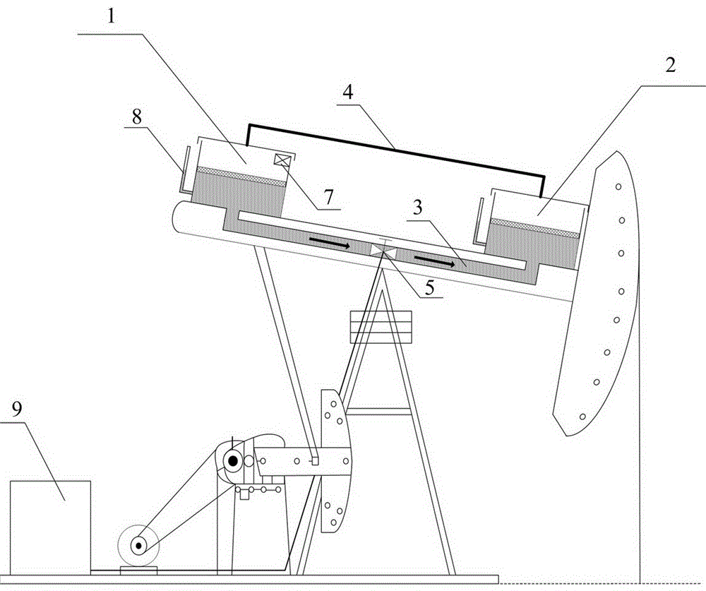
[0032] Specific embodiment one: as figure 1 Shown is the shutdown adjustment method using the gravitational potential energy when the electric control valve (5) is used. The basic principle is to control the flow direction of the liquid by changing the position of the two liquid storage tanks by using the gravitational potential energy. When adjusting the balance, the operator can obtain the current liquid volume of the two liquid storage tanks according to the liquid volume measuring device (7) or the connecting pipe liquid level gauge (8), and calculate how much liquid needs to be exchanged according to the current balance degree. When the estimated liquid level reaches the specified position during the process, stop the adjustment.
[0033] If it is necessary to increase the liquid volume of the first liquid storage tank (1), when the pumping unit is shut down, keep the beam of the pumping unit so that the first liquid storage tank (1) is at the lowest point and the second ...
specific Embodiment 2
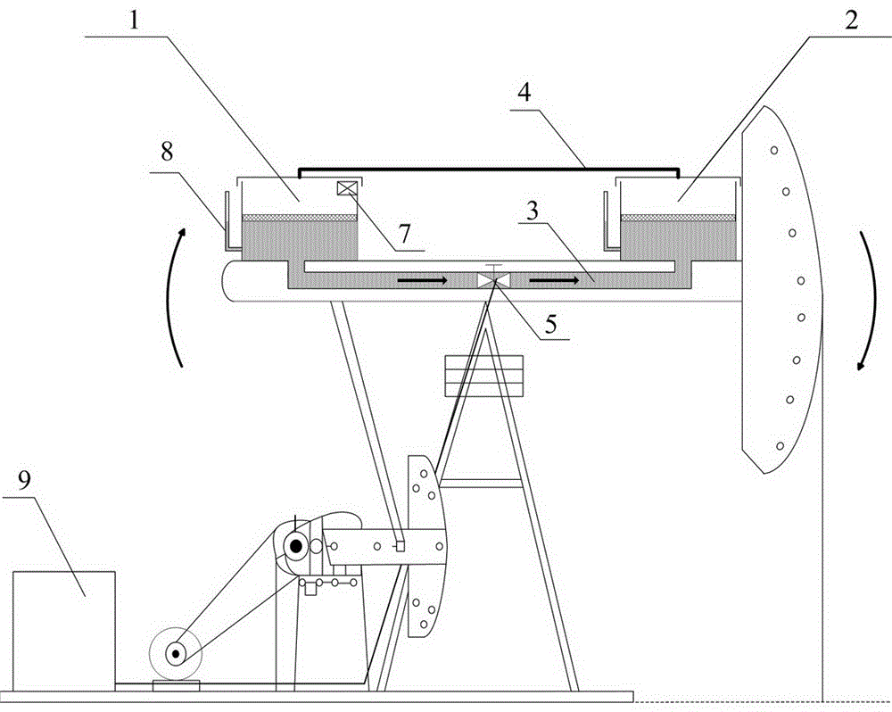
[0034] Specific embodiment two: as figure 2Shown is the non-stop adjustment method using the gravitational potential energy when the electric control valve (5) is used. The operating personnel can obtain the current liquid volumes of the two liquid storage tanks according to the liquid volume measuring device (7) or the connecting pipe liquid level gauge (8), and calculate how much liquid volume needs to be exchanged according to the current balance degree, and estimate the liquid volume during the adjustment process. When the bit reaches the specified position, stop the adjustment.
[0035] If it is necessary to make the liquid flow from the first liquid storage tank (1) to the second liquid storage tank (2), during the up and down movement of the pumping unit, when the first liquid storage tank (1) is in a rising state and its height is the same as that of the second liquid storage tank When the liquid storage tanks (2) are the same, the controller (9) controls the electri...
specific Embodiment 3
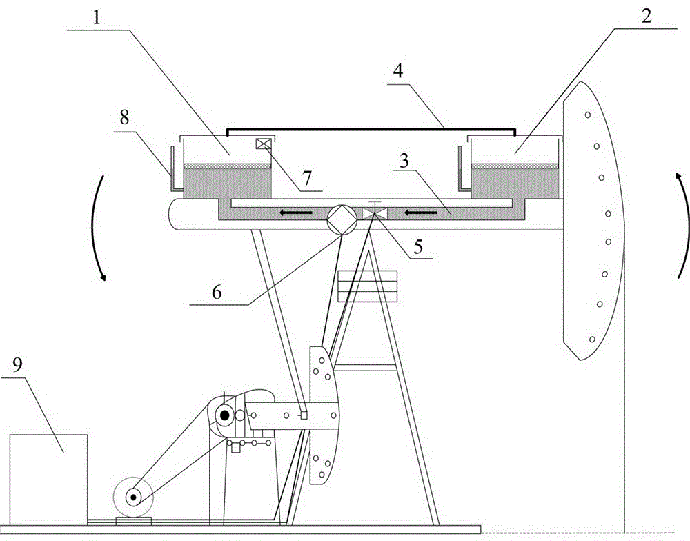
[0037] Specific embodiment three: as image 3 Shown is the non-stop adjustment method using the electronically controlled valve (5) and the two-way water pump (6). The catheter tube (3) of the device is also equipped with a two-way water pump (6). When adjusting the balance, the operator can obtain the current two storage liquids according to the liquid volume measuring device (7) or the liquid level gauge of the connecting pipe (8). The liquid volume of the tank, and calculate how much liquid needs to be exchanged according to the current balance degree, and stop the adjustment when the liquid level is estimated to reach the specified position during the adjustment process.
[0038] If it is necessary to increase the liquid volume of the first liquid storage tank (1), the controller (9) opens the electric control valve (5), and at the same time starts the two-way water pump (6) to work, controls the rotation direction of the two-way water pump (6), and makes the liquid flow f...
PUM
 Abstract
Description
Claims
Application Information