Voltage fluctuation quantitative detection circuit/device

A technology of quantitative detection and detection circuit, applied in the direction of measurement device, measurement of electrical variables, measurement of current/voltage, etc., can solve the problem of not being able to provide more accurate quantitative values ​​in the state of voltage change, not being able to continuously quantitatively track and detect for a long time, and not having quantitative accuracy. Detection and other problems, to achieve the effect of good promotion and application value, light weight and low cost

Active Publication Date: 2017-06-13
郑州伏特电子科技有限公司
View PDF7 Cites 3 Cited by
  • Summary
  • Abstract
  • Description
  • Claims
  • Application Information

AI Technical Summary

Problems solved by technology

However, the currently disclosed detection methods do not have the ability of quantitative and accurate detection, and cannot meet the requirements of quantitative detection in many occasions.
[0003] Chinese invention patent "voltage rise and fall detection circuit and method" (patent number 200810067222.X) discloses a "can realize when the voltage rises or falls, the output detection control voltage signal, cooperate with other control circuits to realize the correlation when the power supply voltage rises" Control action" voltage rise and fall detection circuit, but through the analysis of the public circuit, it can be seen that the sensitivity of the patented method is low, and only when the voltage changes greatly (greater than 0.7V), there is an output, that is, it can only be used for qualitative detection. It cannot be continuously quantitatively tracked and detected for a long time, and cannot provide more accurate quantitative values ​​for the voltage change state of the measured object, and cannot meet the use requirements in many occasions

Method used


Image

  • Voltage fluctuation quantitative detection circuit/device
  • Voltage fluctuation quantitative detection circuit/device
  • Voltage fluctuation quantitative detection circuit/device

Examples


Embodiment 1

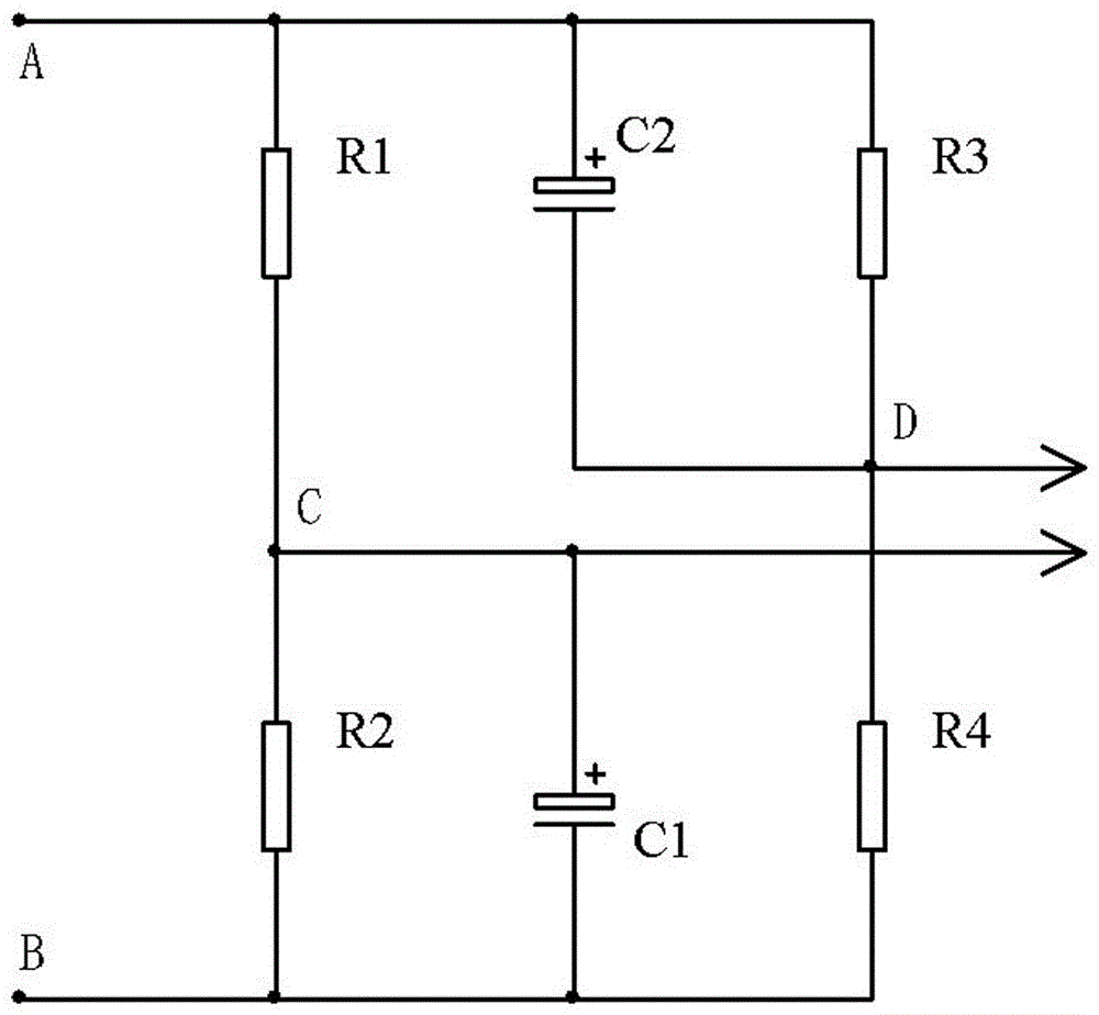
[0020] see figure 1 , the voltage rise and fall quantitative detection device (or circuit, the same below) of the present invention adopts resistance R1 and resistance R2 in series, resistance R3 and resistance R4 in series, and then forms a resistance bridge connected in parallel to the two ends of the object to be detected. A clamping capacitor C1 is set in parallel with the bridge arm resistance, and the resistance bridge and the clamping capacitor C1 together form a terminal voltage change rate detection circuit; the output terminal of the terminal voltage change rate detection circuit is the detected The terminal voltage change signal output terminal of the object outputs the detected voltage change signal to the outside.

[0021] In the voltage rise and fall quantitative detection device of this embodiment, a clamping capacitor C1 is provided on one arm of the resistance bridge, and the detected terminal voltage signal has a relatively small change range.

[0022] In th...

Embodiment 2

[0024] see figure 1 , the voltage rise and fall quantitative detection device (or circuit) of this embodiment is different from Embodiment 1 in that: the diagonal bridge arm of the resistance bridge and the bridge arm resistance are respectively provided with clamping capacitors C1 and C2 in parallel, The resistance bridge and the clamping capacitors C1 and C2 jointly form a terminal voltage change rate detection circuit. The capacitance values ​​of the two clamping capacitors C1 and C2 are correspondingly consistent and equal in size.

[0025] Similarly, when the parameters of each component of the resistance bridge are equal (the corresponding bridge arm resistances are equal), the output is linearly synchronized with the voltage rise, and the amplitude is the largest. When the component values ​​are asymmetrical, the detected signal amplitude decreases and the linearity is distorted.

Embodiment 3

[0027] see figure 1 , the voltage rise and fall quantitative detection device of this embodiment is different from Embodiment 2 in that: in the terminal voltage change rate detection circuit, the resistance values ​​of the two resistors of the upper bridge arm are the same, and the two resistors of the lower bridge arm The resistance values ​​of the two clamping capacitors are the same, and the capacitance values ​​of the two clamping capacitors are equal.

[0028] The working principle of the voltage rise and fall quantitative detection device of this embodiment is as follows:

[0029] When the influence of capacitors C1 and C2 is not considered, no matter how the voltage at both ends of the resistance bridge changes, and no matter how fast the voltage rises, the potentials of nodes C and D rise synchronously and are always equal; after adding capacitors C1 and C2, due to The voltage at both ends of the capacitor cannot change abruptly, and the rising range of the battery te...


PUM


Abstract

The invention relates to a voltage fluctuation quantitative detection circuit / device. According to the voltage fluctuation quantitative detection circuit / device, a resistance bridge is adopted to be connected to the two ends of a to-be-detected object in parallel, in one bridge arm of the resistance bridge, an embedded capacitor is connected with a bridge arm resistor in parallel, and the resistance bridge and the embedded capacitor form a terminal voltage change rate detection circuit together; the output end of the terminal voltage change rate detection circuit is the output end of a terminal voltage change signal of the to-be-detected object, and a detected voltage change signal is output outward. The voltage fluctuation quantitative detection circuit / device is simple in circuit structure and scientific and reasonable in design. The rise and drop of the terminal voltage of the to-be-detected object can be detected, so that qualitative detection is achieved, and moreover, the continuous change of the voltage can be tracked and measured, so that the real-time quantitative detection of the terminal voltage of the to-be-detected object is detected.

Description

technical field [0001] The invention relates to a voltage rise and fall change detection circuit / device. Background technique [0002] In modern electronic circuits or automated electronic instruments and instrumentation equipment, it is often necessary to obtain qualitative or quantitative data of various electrical parameters and changes in key components in power supplies, electrical appliances or circuits, so as to conduct corresponding equipment and components based on these obtained data. Qualitative or quantitative adjustment and control. For example, the current charging process of various electric vehicle batteries and the storage process of solar power generation need to control the charging speed of the battery. However, for different manufacturers, different processes, different quality or different old and new batteries, even the same battery In different charging stages, the requirements for the charging speed are different, which is reflected in the voltage p...

Claims


Application Information

Patent Timeline
Patent Type & Authority Applications(China)
IPC IPC(8): G01R19/00
CPCG01R19/0038
Inventor 徐俊亚
Owner 郑州伏特电子科技有限公司
Why Eureka
Try Eureka