Optical satellite in-orbit imaging simulation method based on wave front inversion

A technology of optical satellites and simulation methods, applied in design optimization/simulation, special data processing applications, instruments, etc., can solve the problem of not fully reflecting the influence of the spatial variation characteristics of the coupling characteristic transfer function on imaging quality, and the inapplicability of diffractive imaging systems And other issues

Active Publication Date: 2017-06-13
HARBIN INST OF TECH
View PDF6 Cites 18 Cited by
  • Summary
  • Abstract
  • Description
  • Claims
  • Application Information

AI Technical Summary

Problems solved by technology

[0004] The purpose of the present invention is to solve the problem that the existing optical satellite on-orbit imaging simulation method cannot fully reflect the coupling characteristics between the parameters of the entire link of optical remote sensing and the influence of the spatial variation characteristics of the transfer function of the imaging system on the imaging quality, and cannot be applied to diffraction In order to solve the problem of traditional imaging system, a simulation method of optical satellite on-orbit imaging based on wavefront inversion is proposed

Method used


Image

  • Optical satellite in-orbit imaging simulation method based on wave front inversion
  • Optical satellite in-orbit imaging simulation method based on wave front inversion
  • Optical satellite in-orbit imaging simulation method based on wave front inversion

Examples


specific Embodiment approach 1

[0024] Specific embodiment one: what this embodiment records is a kind of optical satellite in-orbit imaging simulation method based on wavefront inversion, and described method steps are as follows:

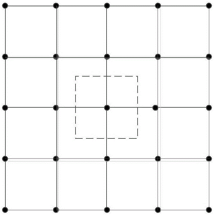
[0025] Step 1: Based on the in-focus image and out-of-focus image of the optical satellite, using the spatial position relationship between the object field of view and the image, the two images are divided into blocks;

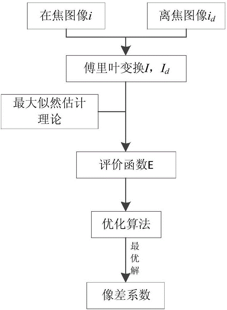
[0026] Step 2: Combining the block results of Step 1, use PD technology to invert the wavefront aberration of each field of view and direction;

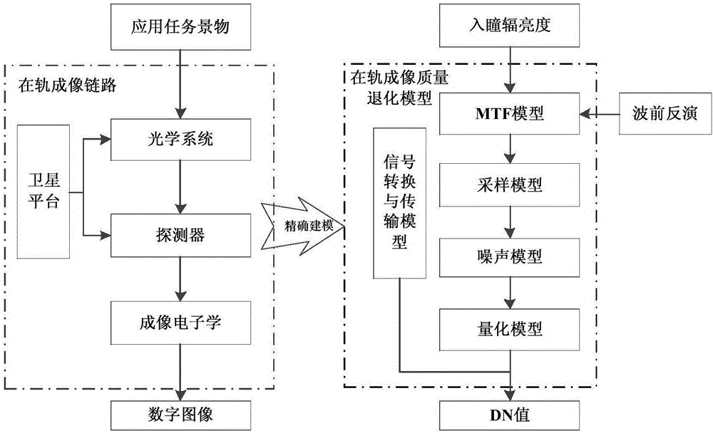
[0027] Step 3: Construct a complex aperture function based on the wavefront aberration calculated in step 2, and perform normalized autocorrelation processing on the complex aperture function to obtain the MTF of different fields of view and directions of the system;

[0028] Step 4: Combining the modeling and characterization of signal transmission and conversion, sampling, noise, and quantization processes, establis...

specific Embodiment approach 2

[0030] Specific embodiment two: a kind of optical satellite on-orbit imaging simulation method based on wavefront inversion described in specific embodiment one, the specific steps of described step one are as follows:

[0031] Firstly, determine the central position of the blocks in different directions and fields of view on the image (for details, refer to the typical fields of view considered in optical design, that is, central field of view, sub-field of view, and full field of view), and select multiple directions on the image evenly, For different fields of view and different directions, select the appropriate block size so that all blocks can cover the entire image, and design overlapping areas between blocks, and adopt different block strategies according to different systems and application requirements.

specific Embodiment approach 3

[0032] Specific embodiment three: a kind of optical satellite on-orbit imaging simulation method based on wavefront inversion described in specific embodiment one, the specific steps of described step two are as follows:

[0033] Combining the block results of step 1, take the center of each block as the origin, establish an orthogonal rectangular coordinate system, and mark the center coordinates of each image block as (x a ,y b );

[0034] Using PD technology, the wave aberration coefficient corresponding to each block is calculated. The wave aberration function is accurately fitted by the Zernike polynomial. The model is:

[0035]

[0036] Where α is the aberration coefficient, K is the total number of items, Zi is the i-th item of the Zernike polynomial, and W is the wavefront aberration;

[0037] Let i(x a ,y b ) is the intensity distribution on a block of the focal plane image, i d (x a ,y b ) is the intensity distribution on the corresponding block of the defo...


PUM


Abstract

The invention discloses an optical satellite in-orbit imaging simulation method based on wave front inversion, and belongs to the technical field of optical imaging simulation. The optical satellite in-orbit imaging simulation method includes the steps: (1) processing images in a partitioning manner by the aid of position relations among object fields and the images based on focused and defocused images of the optical satellite; (2) inverting wave front aberrations of view fields and directions; (3) constructing complex aperture functions, and performing normalized autocorrelation processing on the complex aperture functions to obtain different MTFs (modulation transfer functions); (4) building optical satellite in-orbit imaging quality deterioration models according to modeling characterizations of processes; (5) inputting radiant brightness before entrance pupil of scenes based on the model to simulate top obtain deterioration images. The method can reflect optical remote satellite in-orbit imaging quality deterioration laws and can support optimization design, index demonstration and performance evaluation of an optical remote imaging system and verification and optimization of an image processing algorithm, and the method is applicable to optical satellite in-orbit imaging simulation of a new simulation and diffraction imaging system of a refracted/reflected imaging system.

Description

technical field [0001] The invention belongs to the technical field of optical imaging simulation, in particular to an optical satellite on-orbit imaging simulation method based on wavefront inversion. Background technique [0002] On-orbit imaging quality simulation of optical remote sensing satellites has important theoretical guiding significance and engineering application value in application tasks such as reconnaissance, surveying and mapping, surveillance, imaging performance analysis, imaging system optimization design and performance evaluation, and image processing algorithm optimization. The traditional simulation method is mostly based on the modulation transfer function (MTF) model, which mainly establishes relatively independent MTFs for different links of the optical remote sensing imaging link, and uses the average value of the MTF in the meridional and sagittal directions to simulate the full-view Field, omni-directional MTF. This type of method has the fol...

Claims


Application Information

Patent Timeline
Patent Type & Authority Applications(China)
IPC IPC(8): G06F17/50
CPCG06F30/20
Inventor 智喜洋傅斌张伟于頔胡建明
Owner HARBIN INST OF TECH
Why Eureka
Try Eureka