
Manufacturing method of electric brush

A brush and pre-product technology, applied in the field of brush preparation, can solve the problems of increased calorific value of the brush, reduced service life of the whole machine, reduced service life, etc., and achieves the goals of reducing noise, increasing channels, and dispersing the direction of noise propagation Effect

Active Publication Date: 2017-06-13
CHONGQING HEHAI CARBON PROD
View PDF5 Cites 12 Cited by
  • Summary
  • Abstract
  • Description
  • Claims
  • Application Information

AI Technical Summary

Problems solved by technology

[0003] The high-speed relative rotation between the brushes, commutator and slip rings generates friction noise and friction heat. In addition, the high current commutation sparks accelerate the electric erosion and wear of brushes, commutators and slip rings, reducing the service life; In order to improve the service life, it is necessary to appropriately increase the resistance of the brush to reduce the friction coefficient of the brush, and the increase in resistance will lead to an increase in the calorific value of the brush, so that the temperature rise index will not be guaranteed. The brushes, commutator, and slip rings will heat up. The result of exceeding the allowable temperature is to reduce the service life of the whole machine, and at the same time sacrifice the electrical performance of some brushes; to ensure the electrical performance of the brushes, it is necessary to increase the electrical properties of the brushes. Conductivity, which will lead to an increase in the friction coefficient and reduce the service life of the commutator and slip ring
[0004] High-speed relative rotation motion, friction noise is also not allowed for high-end brush products. If you want to reduce noise by impregnating lubricant and improving the porosity of the material, the effect is also limited

Method used


Image

  • Manufacturing method of electric brush
  • Manufacturing method of electric brush
  • Manufacturing method of electric brush

Examples

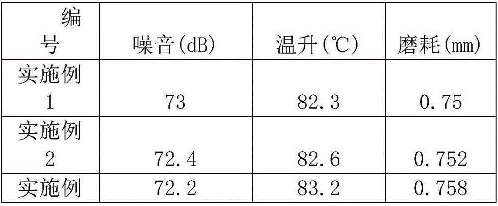

Embodiment Construction

[0024] The present invention will be described in further detail below by means of specific embodiments:

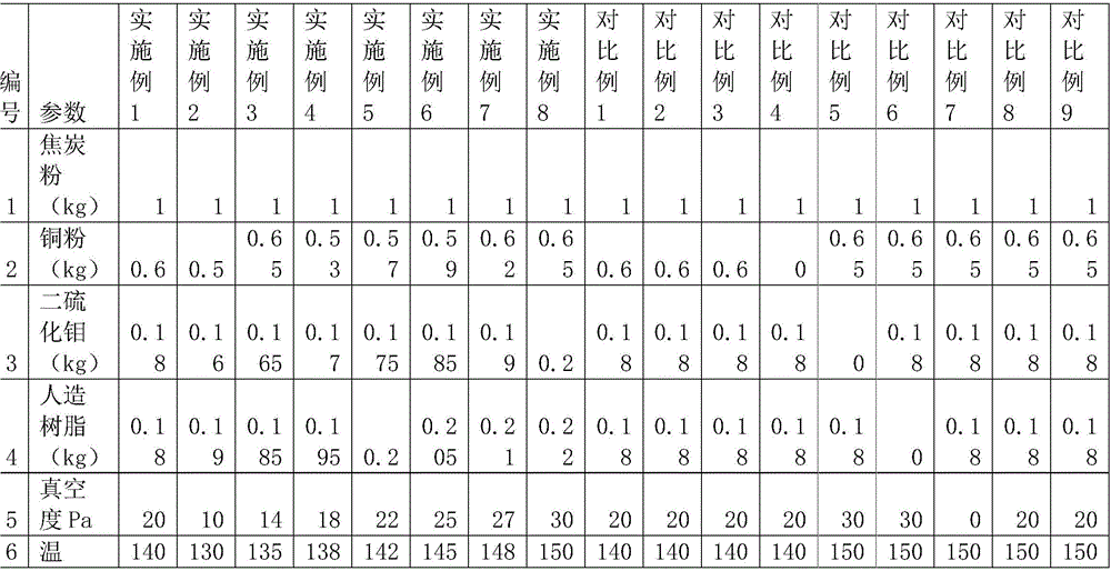
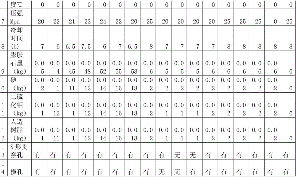
[0025] For the preparation method of a kind of electric brush of this scheme, carried out following embodiment test, as shown in table 1:

[0026] Table 1 A parameter table of a preparation method of an electric brush

[0027]

[0028]

[0029] Step 1: Select raw materials, which are coke powder, metal powder, binder and lubricant;

[0030] Step 2: Get 1kg of coke powder, 0.6kg of copper powder, 0.18kg of artificial resin, 0.18kg of molybdenum disulfide, and mix and stir;

[0031] Step 3: pulverize the mixture obtained in step 2 into powder;

[0032] Step 4: Put the powdery mixture in the mold and pre-press it to form a preform. A number of S-shaped grooves are formed on one side of the preform, and there are several horizontal grooves connected between the S-shaped grooves;

[0033] Step 5: Put the two preforms into a pair, stick the sides of the preforms with S...


PUM


Abstract

The invention discloses a manufacturing method of an electric brush. The manufacturing method includes the steps that raw materials are selected and smashed into powder according to the ratio, and prepressing is carried out on the powder to form a prefabricated part with S-shaped grooves and transverse grooves; the prefabricated part is pressed again to obtain a preliminary processed product, wherein multiple S-shaped through holes are formed in the preliminary processed product, and transverse holes are communicated between the through holes; burrs on the surface of the preliminary processed product are ground off, then the preliminary processed product is sintered in a high-temperature and high-pressure environment, dipped and cooled after sintering, after cooling, filler prepared by mixing expanded graphite, iodine, binder and lubricant is injected into the S-shaped through holes and the transverse holes, and a finished product is obtained through compaction. Compared with the prior art, the manufactured electric brush reduces noise and heat productivity and increases heat dissipating channels in the operation process.

Description

technical field [0001] The invention relates to a preparation process of an electric brush, in particular to a preparation method of an electric brush. Background technique [0002] At present, during the use of brushes, there is a mutually restrictive and contradictory relationship between noise, temperature rise, service life and electrical performance technical indicators. To ensure good electrical performance, other technical indicators must be sacrificed. [0003] The high-speed relative rotation between the brushes, commutator and slip rings generates friction noise and friction heat. In addition, the high current commutation sparks accelerate the electric erosion and wear of brushes, commutators and slip rings, reducing the service life; In order to improve the service life, it is necessary to appropriately increase the resistance of the brush to reduce the friction coefficient of the brush, and the increase in resistance will lead to an increase in the calorific valu...

Claims


Application Information

Patent Timeline
Patent Type & Authority Applications(China)
IPC IPC(8): H01R43/12
CPCH01R43/12
Inventor 曹双全
Owner CHONGQING HEHAI CARBON PROD
Learn More