High-power direct current pulse power supply

A DC pulse power supply, high-power technology, applied in the output power conversion device, electrical components and other directions, can solve the problems of the surrounding electrical equipment can not work normally, the reliability of new power electronic devices is low, and the power grid secondary wave interference, etc. Low loss, low cost, low electromagnetic interference effect

Active Publication Date: 2017-06-13
XIANGTAN ELECTRIC MFG CORP LTD
View PDF3 Cites 4 Cited by
  • Summary
  • Abstract
  • Description
  • Claims
  • Application Information

AI Technical Summary

Problems solved by technology

[0004] It is very difficult to achieve high-power and high-current pulsed DC power supply. Even if such a pulsed DC device is produced with new high-power electronic devices (such as IGBTs and MOSFETs), it is necessary to achieve thousands of amperes to tens of thousands of amperes. The cost of the output current of ampere is also very high, and the economy is difficult to be recognized by the market
At the same time, such a centralized pulse power supply will have the following problems during use: 1. Due to the high tube voltage drop of the IGBT, the efficiency of the device will be lower than that of the traditional rectifier power supply; 2. The pulse current generated periodically by the device will inevitably affect The power grid produces secondary wave interference, which will cause the surrounding electrical equipment to fail to work properly in severe cases; 3. The reliability of new power electronic devices is lower than that of traditional rectifiers, because the overload capacity of IGBTs and MOSFETs is much lower than that of rectifiers and thyristors, and the drive requirements high

Method used


Image

  • High-power direct current pulse power supply
  • High-power direct current pulse power supply
  • High-power direct current pulse power supply

Examples


Embodiment Construction

[0023] The present invention will be further described below in conjunction with the accompanying drawings and embodiments.

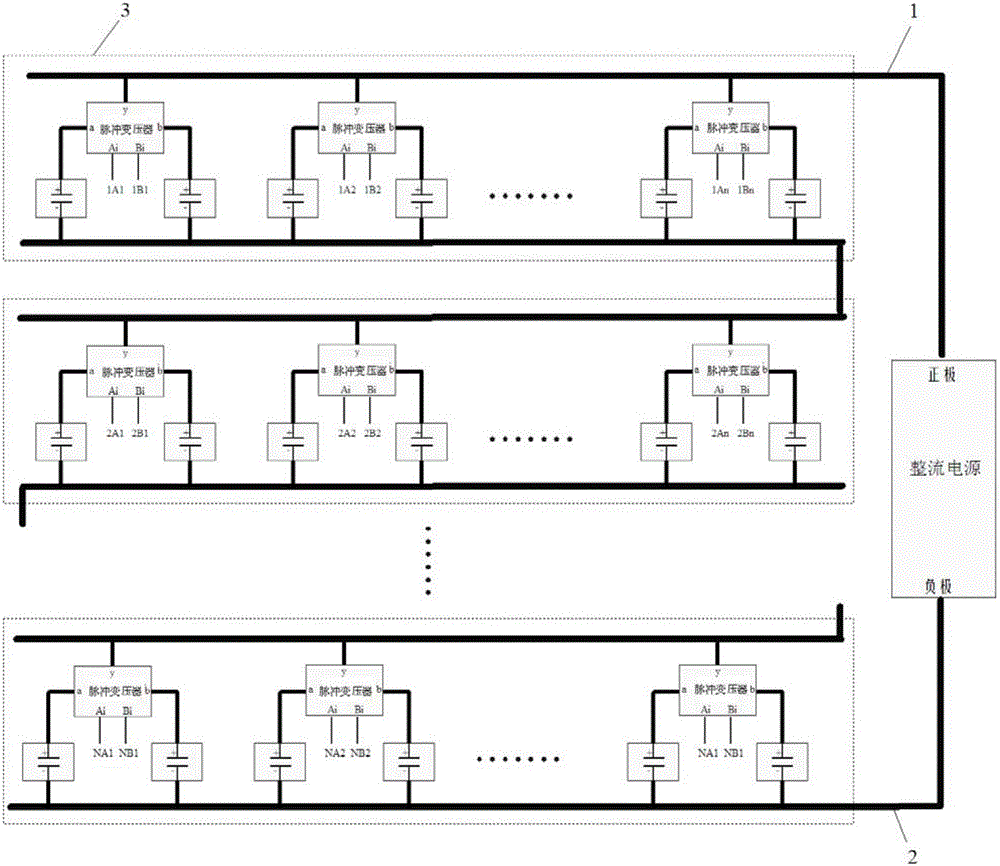
[0024] Such as figure 1 As shown, the present invention includes a rectifying power supply, a positive busbar 1, a negative busbar 2, a pulse controller and a plurality of basic units 3, the positive pole of the rectifying power supply is connected to the positive busbar 1, and the negative pole of the rectifying power supply is connected to the positive pole busbar 1. The negative busbar 2 is connected, and a plurality of basic units 3 are arranged in parallel between the positive busbar 1 and the negative busbar 2 , and the pulse controller is connected to each basic unit 3 .

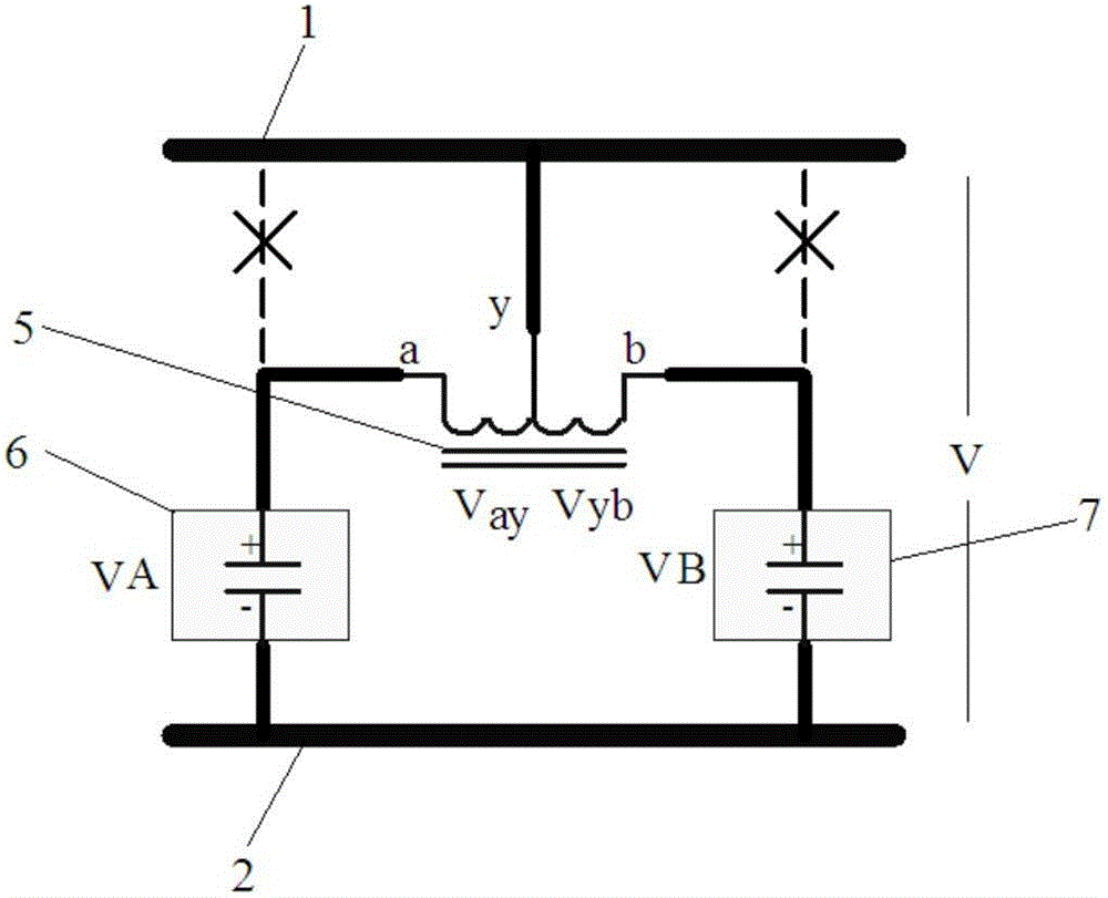
[0025] Such as image 3 , Figure 4 As shown, the basic unit 3 includes several electrolytic unit groups connected in parallel, and each electrolytic unit group includes a pulse transformer 5, a first electrolytic unit 6, a second electrolytic unit 7, a pulse working power su...


PUM


Abstract

The invention discloses a high-power direct current pulse power supply. The high-power direct current pulse power supply comprises a rectification power supply, a positive pole confluence busbar, a negative pole confluence busbar, a pulse controller and multiple basic units; a positive pole of the rectification power supply is connected with the positive pole confluence busbar, a negative pole of the rectification power supply is connected with a negative pole confluence busbar, the multiple basic units are arranged between the positive pole confluence busbar and the negative pole confluence busbar in parallel, and the pulse controller is connected with each basic unit. The high-power direct current pulse power supply has the advantages that each electrolysis unit adopts a distributed structure, pulse direct current power supply is realized for each electrolysis unit by virtue of a pulse transformer provided with a pulse driving tube and by utilizing a magnetic balance principle and vector superposition effect of electric quantity, capacity is not limited, demand of pulse power supplies in any specification and at any voltage and current grades can be met, and a transformer is adopted as a pulse generating element, so that loss of the high-power direct current pulse power supply is far lower than on-state loss of power electronic devices such as an IGBT and an MOSFET.

Description

technical field [0001] The invention relates to the field of storage battery charging, in particular to a high-power DC pulse power supply. Background technique [0002] In the electrochemical field, the DC power supply required for electrolytic production generally has thousands of amperes to tens of thousands of amperes. Most of these power supply devices are composed of rectifier transformers and diode rectifiers or thyristor rectifiers, which can only output fixed or variable amplitude. tuned DC current. In the electrochemical production process, it is particularly hoped that this direct current can be converted into a pulsed direct current and output to the electrolytic cell under specific conditions. For example, in the production process of potassium perchlorate, if pulsed direct current can effectively solve the problems of plate surface deposition and electrode surface polarization effects, improve conversion efficiency, reduce cleaning time, and reduce labor inten...

Claims


Application Information

Patent Timeline
Patent Type & Authority Applications(China)
IPC IPC(8): H02M9/02
CPCH02M11/00
Inventor 冯大唯宋焱秋肖文平戴洁王卉
Owner XIANGTAN ELECTRIC MFG CORP LTD
Why Eureka
Try Eureka