
Signal amplification frequency compensation circuit applicable to RFID (Radio Frequency Identification) reader

A signal amplification and frequency compensation technology, applied in the field of signal processing, can solve problems such as affecting the stability of operational amplifiers

Inactive Publication Date: 2017-06-13
GUANGZHOU SYSUR MICROELECTRONICS +1
View PDF4 Cites 0 Cited by
  • Summary
  • Abstract
  • Description
  • Claims
  • Application Information

AI Technical Summary

Problems solved by technology

However, each gain stage has at least one high-impedance node, forming a low-frequency pole. These low-frequency poles will affect the stability of the op amp itself, so it needs to be frequency compensated

Method used


Image

  • Signal amplification frequency compensation circuit applicable to RFID (Radio Frequency Identification) reader
  • Signal amplification frequency compensation circuit applicable to RFID (Radio Frequency Identification) reader

Examples


Embodiment Construction

[0042] The following will clearly and completely describe the technical solutions in the embodiments of the present invention with reference to the accompanying drawings in the embodiments of the present invention. Obviously, the described embodiments are only some, not all, embodiments of the present invention. Based on the embodiments of the present invention, all other embodiments obtained by persons of ordinary skill in the art without creative efforts fall within the protection scope of the present invention.

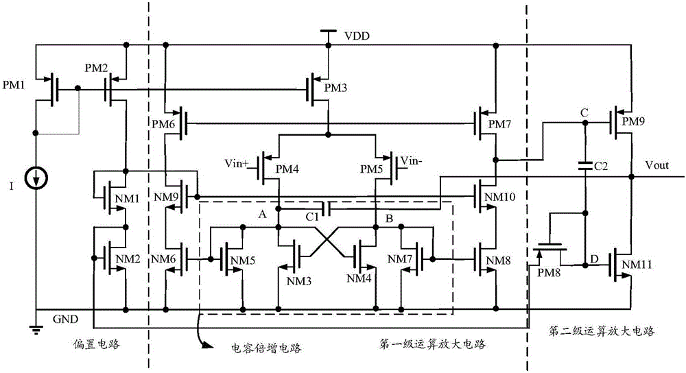
[0043] figure 1 It is a circuit structure composition diagram of the signal amplification frequency compensation circuit in the embodiment of the present invention, as figure 1 As shown, the signal amplification frequency compensation circuit includes: a bias circuit, a first-stage operational amplifier circuit and a second-stage operational amplifier circuit;

[0044] The bias circuit is used to provide a temperature-independent stable voltage for the operation o...


PUM


Abstract

The invention discloses a signal amplification frequency compensation circuit applicable to an RFID (Radio Frequency Identification) reader. The signal amplification frequency compensation circuit comprises a bias circuit, a first stage operational amplifier circuit and a second stage operational amplifier circuit; the bias circuit is used for providing a temperature independent stable voltage for the first stage operational amplifier circuit and the second stage operational amplifier circuit to work; the first stage operational amplifier circuit is used for receiving a signal frequency to be amplified, performing first operation amplification processing on the signal frequency to be amplified, and acquiring a first amplified signal frequency; and the second stage operational amplifier circuit is used for performing second operation amplification processing on the first amplified signal frequency, acquiring an amplified signal frequency, and outputting the amplified signal frequency. In the embodiment of the invention, a capacitance multiplication technology with a voltage-controlled current source is designed, which improves the unity gain bandwidth and meanwhile reduces the offset voltage and obtains a greater slew rate, so as to make a loop more stable, reliable and accurate.

Description

technical field [0001] The invention relates to the technical field of signal processing, in particular to a signal amplification frequency compensation circuit for an RFID reader. Background technique [0002] Radio frequency identification (RadfoFrequencyIdentification, referred to as RFID) technology is a non-contact automatic identification technology, which transmits signals through electromagnetic waves or inductive coupling to complete automatic identification of target objects. Compared with other automatic identification technologies such as barcodes, magnetic cards, and contact IC cards, RFID technology has the advantages of no manual intervention in the identification process, multiple targets can be identified at the same time, a large amount of information storage, and it can work in various harsh environments. Therefore, RFID technology has been widely used in fixed asset management, production line automation, animal and vehicle identification, road toll colle...

Claims


Application Information

Patent Timeline
IPC IPC(8): H03F1/30H03F3/45
CPCH03F1/30H03F3/45394
Inventor 胡建国吴劲吴江旭王德明段志奎
Owner GUANGZHOU SYSUR MICROELECTRONICS
Learn More