FIR filter design method based on two-level optimization and device thereof

A filter design and filter technology, applied in impedance networks, digital technology networks, electrical components, etc., can solve problems such as slow iterative calculation, complex single-variable optimization problems, and large resource consumption, achieving high design efficiency, excellent The effect of transmission performance

Inactive Publication Date: 2017-06-13
TIANJIN UNIV
View PDF3 Cites 3 Cited by
  • Summary
  • Abstract
  • Description
  • Claims
  • Application Information

AI Technical Summary

Problems solved by technology

Second, these optimization design methods are multivariate optimization problems that require optimization of all filter coefficients, which are more complex than univariate optimization problems
Similar to slow natural biological evolution, these evolutionary algorithms consume a large number of iterations and are also computationally slow and resource-intensive
Therefore, the optimization method is not competent for the design task of high-order FIR filter

Method used


Image

  • FIR filter design method based on two-level optimization and device thereof
  • FIR filter design method based on two-level optimization and device thereof
  • FIR filter design method based on two-level optimization and device thereof

Examples


Embodiment 1

[0049] A kind of FIR filter design method based on two-level optimization, this method comprises the following steps:

[0050] 101: Obtain the length of the frequency sampling vector and the boundary integer according to the cutoff frequency and the filter transition band, and construct the frequency sampling vector;

[0051] Wherein, this step is specifically: given engineering requirement cut-off frequency ω c , filter transition band Determine frequency sample vector length for filter and boundary integer M=[ω c / (2π / N)+1], and then construct the frequency sampling vector (Initialization T=1).

[0052] 102: first-level optimization;

[0053] The filter coefficient g(n) is obtained through a three-step design method. The specific steps are: given T, the filter coefficient g(n) is obtained according to the following three-step design method:

[0054] 1. The frequency sampling vector H T Perform IDFT transformation to get h=[h(0),h(1),...,h(N-1)], and then perform cy...

Embodiment 2

[0062] The scheme in embodiment 1 is introduced in detail below in conjunction with specific calculation formulas, see the following description for details:

[0063] 201: Filter design based on cyclic shift synthesis;

[0064] 1. Cyclic shift synthesis and natural optimization

[0065] The classical frequency sampling method specifies a frequency sampling vector H=[H(0),H(1),. ...,H(N-1)], which can be set as the following form

[0066]

[0067] Directly perform IDFT on H to get

[0068]

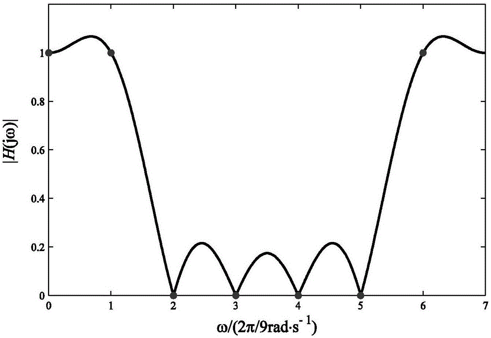
[0069] A cyclic shift of length (N-1) / 2 is performed on the elements in h to obtain the final filter coefficients. Take N=7, M=2 as an example, at this time H=[1 1 0 0 0 0 1] and its IDFT vector is h=[h(0),...,h(N-1)]= [0.4286 0.3210 0.0793 -0.1146 -0.1146 0.0793 0.3210]. So after the cyclic shift, the final filter coefficients can be obtained as

[0070] However, if figure 1 As shown, although the amplitude-frequency curve of the filter is at ω=k2π / N, k=0,..., N-1 frequency ...

Embodiment 3

[0161] The scheme in embodiment 1 and 2 is further introduced below in conjunction with specific calculation formula, example, see the following description for details:

[0162] Experiment 1. The performance effect of the filter designed in the embodiment of the present invention:

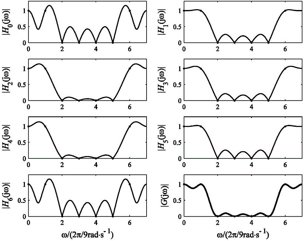
[0163] This experiment aims to compare the performance of the windowed cyclic shift synthesis proposed by the embodiment of the present invention with its DE-optimized filter.

[0164] parameter settings with figure 2 Same, N=7, M=2, w c (n)=f(n)*R N (-n), where f(n) is a Hamming window of length N. Table 1 lists the control parameters in the initialization phase of the DE algorithm.

[0165] Table 1. Control parameters of the DE algorithm

[0166]

[0167]

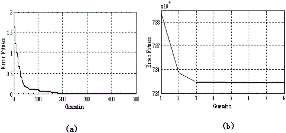
[0168] according to Figure 8 According to the design steps, the optimal transition point value T=0.9480 can be obtained, and the filter coefficient g corresponding to it can be calculated by the 3-step design method T (n), and ...


PUM


Abstract

The invention discloses an FIR filter design method based on two-level optimization and a device thereof. The method comprises the steps of carrying out IDFT on a frequency sampling vector, thereby obtaining a transformed vector, and carrying out cyclic shift processing, thereby obtaining a shifted vector; selecting a common window with a length of N, carrying out convolution and normalization on the common window and a rectangular window, thereby obtaining a convolution window with the length of 2N-1; carrying out point multiplication on the shifted vector and the 2N-1 convolution window, thereby obtaining an FIR filter analysis coefficient; further optimizing the FIR filter analysis coefficient through utilization of an evolution strategy, obtaining a transition value and establishing the frequency sampling vector; and finding the globally optimum transition value, and further obtaining the final FIR filter coefficient. According to the method and the device, two-level optimization is applied; a high-performance FIR filter with small transmission curve passband ripples and high stopband attenuation is designed; the calculation complexity of an existing evolution optimization filter design method is reduced; and the design efficiency is improved.

Description

technical field [0001] The invention relates to the technical field of digital signal processing, in particular to a two-level optimization-based FIR filter design method and a device thereof. Background technique [0002] Efficient design of linear-phase FIR filters is widely required in the fields of software radio [1], multi-rate signal processing [2] and signal detection [3]. As we all know, the design of FIR filter is essentially an optimization problem, and its task is to obtain a set of filter coefficients that are close to the ideal frequency response after Fourier transform. The current FIR filter design methods are mainly divided into two categories: the first category is the classical design method, mainly including the window function method and the frequency sampling method; the second category is the optimization algorithm, mainly including the Parks-McClellan method [4], Genetic algorithm (Genetic algorithm, GA) [5], particle swarm optimization algorithm (Par...

Claims


Application Information

Patent Timeline
IPC IPC(8): H03H17/06
Inventor 黄翔东张博马欣
Owner TIANJIN UNIV
Why Eureka
Try Eureka