Small-size oscillation grain dehuller

A technology of oscillating mechanism and grain, applied in the direction of solid separation, sieve, grille, etc., can solve the problems of high labor intensity, complete removal, mixing, etc., achieve the effect of large blowing coverage, avoid rigid contact, and improve efficiency

Inactive Publication Date: 2017-06-20
奥林精密机械科技(长兴)有限公司
View PDF1 Cites 20 Cited by
  • Summary
  • Abstract
  • Description
  • Claims
  • Application Information

AI Technical Summary

Problems solved by technology

[0003] After the drying process of the grain, the grain husk of the outer layer of the grain needs to be dehulled; in the traditional husk processing process, due to the light weight and small size of the grain husk, it is easy to be mixed in the hulled grain; while the traditional During the dehusking process, the exhaust fan is elevated, and then the worker bends down to fill the hulled grains into the pan, straightens up and lifts the pan so that the pan is higher than the exhaust fan, and then pours the grains in the pan When these grains pass through the wind blown by the exhaust fan, the grain husks mixed in the grains can be blown away, so that the grains are separated from the grain husks; however, this traditional i

Method used


Image

  • Small-size oscillation grain dehuller
  • Small-size oscillation grain dehuller
  • Small-size oscillation grain dehuller

Examples


Embodiment 1

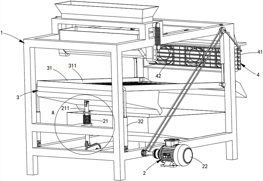
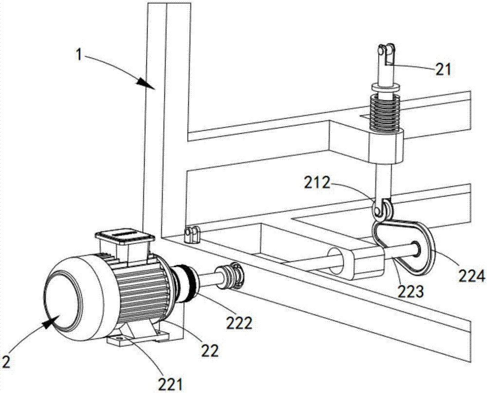
[0042] Such as figure 1 As shown, a small vibrating grain sheller includes a frame 1, an oscillating mechanism 2, a screening mechanism 3 and an air outlet mechanism 4. Assembly 21 and drive assembly 22, the oscillation assembly 21 is slidably arranged on the frame 1, and the drive assembly 22 is provided on one side thereof, the drive assembly 22 drives the oscillation arm 211 in the oscillation assembly 21 along the frame 1 up and down movement;

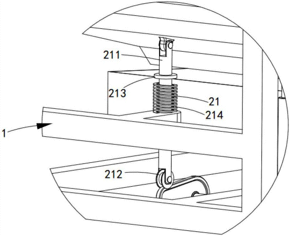
[0043] The screening mechanism 3 is arranged above the oscillating mechanism 2, and it includes a screening assembly 31 and an elastic connection assembly 32. 211 hinged, the vibrating arm 211 drives the screening net 311 in the screening assembly 31 to vibrate up and down, the elastic connecting assembly 32 is arranged at both ends of the screening assembly 31, one end is connected with the screening net 311, and the other end is connected with the screening net 311. The rack 1 is connected;

[0044] The air outlet mechanism 4 ...

Embodiment 2

[0066] Figure 10 It is a schematic structural view of Embodiment 2 of a small vibrating grain huller of the present invention; as Figure 10 As shown, the components that are the same as or corresponding to those in the first embodiment are marked with the corresponding reference numerals in the first embodiment. For the sake of simplicity, only the differences from the first embodiment will be described below. This embodiment two and figure 1 The difference of the shown embodiment one is:

[0067] Such as Figure 10 As shown, a small vibrating grain huller also includes an intermittent feeding mechanism 5 fixedly arranged on the top of the frame 1, and the intermittent feeding mechanism 5 is located above the screening mechanism 3, and it is used for screening Mechanism 3 performs intermittent feeding, and the intermittent feeding mechanism 5 includes a feed hopper 51, an overturning material box 52, a tension spring 53 and a third elastic connector 54, and the feed hoppe...


PUM


Abstract

The invention discloses a small oscillating grain hulling machine, which comprises a frame, an oscillating mechanism, a screening mechanism and an air outlet mechanism. The air outlet component and the damper component drive the vibration component to run through the driving component. After the vibration component pushes the screening net in the screening component to a high place, the screening net drops rapidly by gravity, throws the grain on the screening net into the air, and is removed by the wind component. Light impurities such as chaff in the grain, and then the grain is returned to the screening net, and the granular impurities in the grain are screened and removed by the screening net. Repeat this process to completely remove the chaff impurities and granular impurities in the grain, and improve the screening efficiency.

Description

[0001] machine technology [0002] The invention relates to the technical field of industrial grain screening and impurity removal, in particular to a small vibrating grain hulling machine. Background technique [0003] After the drying process of the grain, the grain husk of the outer layer of the grain needs to be dehulled; in the traditional husk processing process, due to the light weight and small size of the grain husk, it is easy to be mixed in the hulled grain; while the traditional During the dehusking process, the exhaust fan is elevated, and then the worker bends down to fill the hulled grains into the pan, straightens up and lifts the pan so that the pan is higher than the exhaust fan, and then pours the grains in the pan When these grains pass through the wind blown by the exhaust fan, the grain husks mixed in the grains can be blown away, so that the grains are separated from the grain husks; however, this traditional impurity removal device makes the labor inten...

Claims


Application Information

Patent Timeline
IPC IPC(8): B07B9/00B07B1/28B07B1/46B07B1/42B07B4/08B07B11/02
CPCB07B9/00B07B1/28B07B1/42B07B1/46B07B4/08B07B11/02
Inventor 干贤忠
Owner 奥林精密机械科技(长兴)有限公司
Why Eureka
Try Eureka