Composite frame system with beam column flanges being made of steel pipe concrete and construction method

A technology of steel pipe concrete and frame system, applied in the direction of columns, pier columns, pillars, etc., can solve the problems of cumbersome construction, poor connection stability of composite structures, and easy damage of nodes, so as to achieve good overall structural continuity, shorten construction period, reduce workload effect

Active Publication Date: 2017-06-20
青岛义和钢构集团控股有限公司
View PDF4 Cites 23 Cited by
  • Summary
  • Abstract
  • Description
  • Claims
  • Application Information

AI Technical Summary

Problems solved by technology

[0003] An object of the present invention is to provide a composite frame system in which the beam and column flanges are steel pipe concrete, which is used to solve the complicated construction of existing steel-concrete composite structures, the connection and stability of the composite structures In view of the problems of poor stability and easy damage of joints under earthquake action, another object of the present invention is to provide a construction method for a composite frame system in which the beam-column flanges are steel pipe concrete

Method used


Image

  • Composite frame system with beam column flanges being made of steel pipe concrete and construction method
  • Composite frame system with beam column flanges being made of steel pipe concrete and construction method
  • Composite frame system with beam column flanges being made of steel pipe concrete and construction method

Examples


Embodiment 1

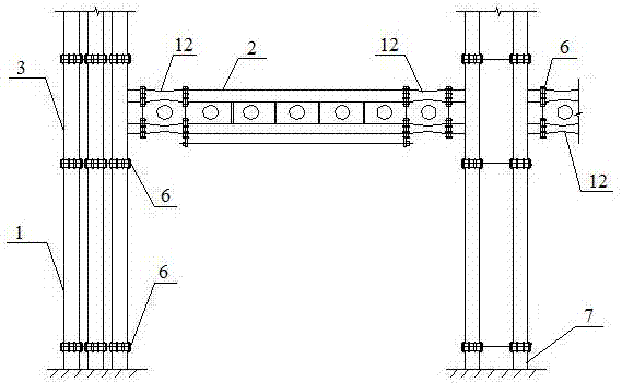
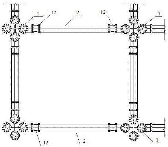
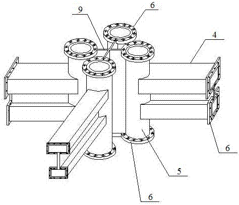
[0043] combine figure 1 , figure 2 , image 3 , Figure 4 , Image 6 , Figure 7 , Figure 8 , Figure 9 As shown, the composite frame system with beam-column flanges made of concrete-filled steel tube is composed of composite column 1 and composite beam 2 connected by node 3, composite beam 2 is horizontally arranged between composite columns 1, node 3 is an integral node of steel tube concrete, and steel tube Concrete monolithic joints are welded together with I-shaped node end beams 4 whose upper and lower flanges are steel pipes and node end columns 5 whose flanges are circular steel pipes 8. The joints between I-shaped node end beams 4 and node end columns 5 The rectangular steel pipe 11 of the rectangular steel pipe 11 communicates with the circular steel pipe 8 to form a steel pipe integral joint. Pouring concrete 10; the composite column 1 is a cross-shaped composite column with a circular steel pipe concrete flange, and the two ends of the circular steel pipe ...

Embodiment 2

[0051] combine figure 1 , figure 2 , Figure 10 , Figure 11 , Figure 12 , Figure 13 , Figure 14 As shown, the composite frame system with beam-column flanges made of concrete-filled steel tube is composed of composite column 1 and composite beam 2 connected by node 3, composite beam 2 is horizontally arranged between composite columns 1, node 3 is an integral node of steel tube concrete, and steel tube Concrete monolithic joints are welded together with I-shaped node end beams 4 whose upper and lower flanges are steel pipes and node end columns 5 whose flanges are circular steel pipes 8. The joints between I-shaped node end beams 4 and node end columns 5 The circular steel pipes 8 communicate with each other to form a steel pipe integral joint. The other end of the I-shaped joint end beam 4 is welded with the connecting plate 6, and the two ends of the joint end column 5 are respectively welded with the connecting plate 6. Concrete is poured in the steel pipe integra...

Embodiment 3

[0059] combine figure 1 , figure 2 , Figure 5 As shown, the composite column in this embodiment is a cross-shaped composite column whose flange is circular steel pipe concrete, and the integral joint of steel pipe concrete is an I-shaped node whose upper and lower flanges are circular steel pipes, and the end beams and flanges are circular steel pipes8 The cross-shaped node end column is welded into one, and the circular steel pipe 8 at the junction of the I-shaped node end beam and the node end column is connected to form a steel pipe integral node. The other end of the I-shaped node end beam is welded with a connecting plate. The two ends of the node end column 5 are respectively welded with the connection plate 6, and the concrete 10 is poured in the steel pipe integral node, and the other is the same as the embodiment 2.

[0060] The construction method of the composite frame system in which the above-mentioned beam-column flanges are steel tube concrete:

[0061]Firs...


PUM


Abstract

The invention relates to a composite frame system with beam column flanges being made of steel pipe concrete and a construction method. The composite frame system with the beam column flanges being made of the steel pipe concrete is formed by connecting composite columns with composite beams through joints. The composite beams are horizontally arranged among the composite columns. The joints are steel pipe concrete integral type joints. The composite columns are cross-shaped or I-shaped composite columns with the flanges being made of the circular steel pipe concrete. The composite beams are I-shaped honeycombed beams with the flanges being made of the steel pipe concrete. The joints and the composite columns are fixedly connected at respective connecting plates through high-strength bolts. The joints and the composite beams are connected through buffer sections which are I-shaped honeycombed beams with the flanges being made of the steel pipe concrete. The cross sections of the buffer sections are variable cross sections gradually diminished from the two ends to the centers, and the cross sections of the buffer sections are smallest at the midpoints. The problems that according to an existing steel-concrete composite structure, construction is complex, connection and stability between the composite structure are poor, and the joints are liable to damage under the earthquake effect are solved.

Description

technical field [0001] The invention relates to a building frame structure in the field of civil and architectural structures, in particular to a composite frame system and a construction method in which the flanges of beams and columns are made of steel tube concrete. Background technique [0002] Conventional building frame structures are mostly cast-in-place welded reinforced concrete frames or steel frames, which have a long construction period, are greatly affected by the environment, and the achievable span is small, and the component bearing capacity is low. It has great application in practical engineering. limitation. In recent years, with the development of buildings in the direction of faster, higher, larger span and stronger bearing capacity, conventional structural systems and construction methods are facing new challenges. People began to build structural systems with more convenient construction and stronger bearing capacity. Set the steel frame into a detac...

Claims


Application Information

Patent Timeline
Patent Type & Authority Applications(China)
IPC IPC(8): E04B1/18E04B1/30E04B1/58E04C3/293E04C3/32E04C3/34
CPCE04B1/18E04B1/185E04B1/30E04C3/293E04C3/32E04C3/34
Inventor 计静徐智超张文福张云峰卢召红刘迎春
Owner 青岛义和钢构集团控股有限公司
Why Eureka
Try Eureka