
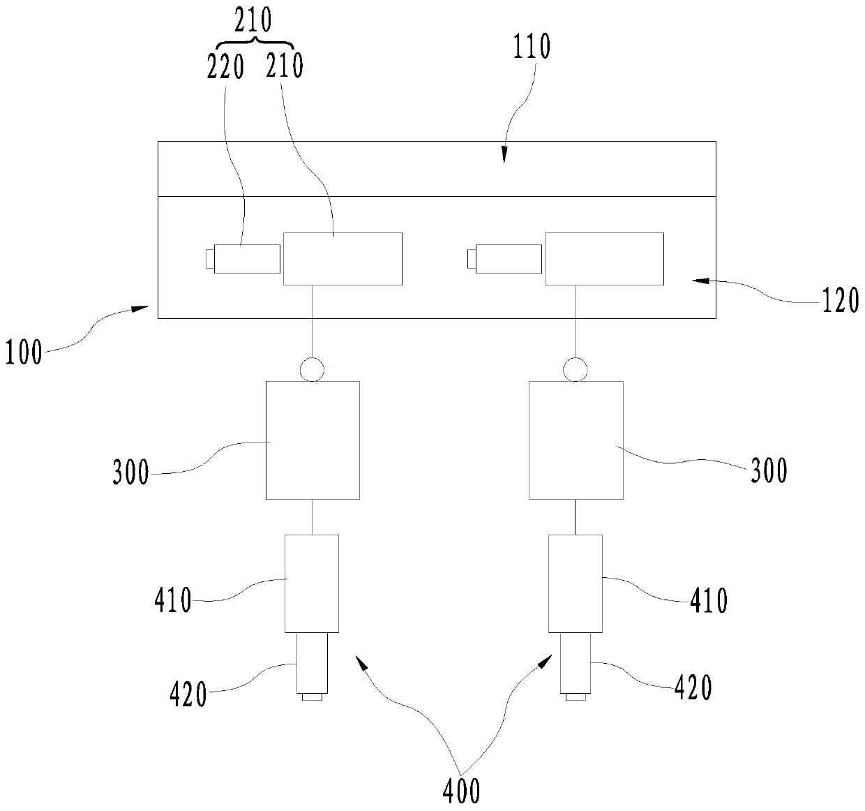
Layout structure of gas-steam combined cycle distributed energy station

A distributed energy and combined cycle technology, applied in industrial buildings and other directions, can solve problems such as large pipeline pressure drop, poor economy, and occupying auxiliary workshop layout space.

Active Publication Date: 2020-04-21
CHINA ENERGY ENG GRP GUANGDONG ELECTRIC POWER DESIGN INST CO LTD
View PDF5 Cites 0 Cited by
  • Summary
  • Abstract
  • Description
  • Claims
  • Application Information

AI Technical Summary

Problems solved by technology

[0005] However, the auxiliary plant is arranged between the main span and the boiler, which will cause the steam pipes, feed water, cooling water and other pipes between the boiler, gas turbine and the main plant to cross the auxiliary span, increasing the length of the pipeline, high initial investment, and pressure on the pipeline. In addition, the pipes crossing the auxiliary span will also occupy the layout space of the auxiliary plant, reducing the effective utilization of the space of the auxiliary plant; at the same time, it also increases the heat engine piping layout and Electrical and control equipment, crossing and mutual influence of cables, poor safety; generator outlet of steam turbine generator set is long, and investment is high

Method used


Image

  • Layout structure of gas-steam combined cycle distributed energy station

Examples


Embodiment Construction

[0025] In order to make the object, technical solution and advantages of the present invention clearer, the present invention will be further described in detail below in conjunction with the accompanying drawings and specific implementation methods. It should be understood that the specific embodiments described here are only used to explain the present invention, and do not limit the protection scope of the present invention.

[0026] It should be noted that when an element is referred to as being “fixed on”, “disposed on” or “installed on” another element, it may be directly on the other element or there may be an intervening element. When an element is considered to be "connected" to another element, it may be directly connected to the other element or there may be an intervening element at the same time; the specific way that one element is fixedly connected to another element can be realized through existing technologies, and will not be discussed here. Let me repeat.

...


PUM


Abstract

The invention discloses a gas and steam combined cycle distributed energy station arrangement structure which comprises a main power house, steam turbine generating sets, waste heat utilization devices and gas turbine generating sets. The main power house comprises an auxiliary power house, and a steam engine room adjacent to the auxiliary power house, the auxiliary power house is arranged at one side of the steam engine room; the steam turbine generating sets are arranged in the steam engine room; the waste heat utilization devices are closely adjacent to the side, away from the auxiliary power house, of the steam engine room, and the waste heat utilization devices are connected with the steam turbine generating sets through pipelines; and the gas turbine generating sets are arranged at the air inlet ends of the waste heat utilization devices, and connected with the waste heat utilization devices through pipelines. Thus, the situation that steam pipelines, water supply pipelines, cooling water pipelines and other pipelines between the waste heat utilization devices (boilers), gas turbines and the main power house stretch across the auxiliary power house is avoided, accordingly the length of the pipelines and cables is shortened, and the pipeline pressure drop degree is lowered, building investment is lowered, and the economic efficiency is improved; and in addition, the space occupied in the auxiliary power house can be reduced, and the space utility rate of the auxiliary power house is increased.

Description

technical field [0001] The invention relates to the technical field of power plant design, in particular to an arrangement structure of a gas-steam combined cycle distributed energy station. Background technique [0002] Energy shortage and environmental degradation have gradually become increasingly serious global problems. The gas-steam combined cycle distributed energy station supplies electricity, heat, and cold at the same time, and uses cascaded energy. It has the characteristics of high efficiency, energy saving, consumption reduction, and flexible operation. At the same time, it can also improve the power structure, cut peaks and fill valleys, and improve energy supply security. It is the main energy supply method that conforms to the trend of national energy development. [0003] For the gas-steam combined cycle distributed energy station, the main plant is one of the core buildings, where most of the host equipment, main thermal system process pipelines, cables, a...

Claims


Application Information

Patent Timeline
Patent Type & Authority Patents(China)
IPC IPC(8): E04H5/02
CPCE04H5/02
Inventor 黄镜欢黄长华李鹏沙励牛亚兵印佳敏王新丽刘俊章正传
Owner CHINA ENERGY ENG GRP GUANGDONG ELECTRIC POWER DESIGN INST CO LTD
Learn More