Thermal Insulation Construction Technology of LNG Cryogenic Transmission Pipeline

A technology for liquefied petroleum and transportation pipelines, applied in thermal insulation, pipeline protection, heat exchange equipment, etc., can solve the problems of reduced pipeline insulation capacity, poor weather resistance of molds, failure of thermal insulation effect, etc., to reduce labor intensity and achieve good performance , Improve the effect of heat insulation

Active Publication Date: 2018-11-27
CHINA NAT OFFSHORE OIL CORP +2
View PDF5 Cites 0 Cited by
  • Summary
  • Abstract
  • Description
  • Claims
  • Application Information

AI Technical Summary

Problems solved by technology

[0008] For the casing insulation layer larger than 3mm, if the above-mentioned existing heat insulation technology is used for construction, a large construction space is required between the pipelines to fix the mold, and the mold has poor weather resistance; if there is cross-operation with on-site welding operations, etc. It is easy to cause the material to be flammable, increase the safety hazard, and pollute the human body and the environment during the construction of the material; and because the pipeline is nearly 100 meters long, the perfusion power is also insufficient; if the outer sheath is damaged, the capillary phenomenon between the fibers and the Electrostatic adsorption, under the action of sunlight and high temperature, the fiber becomes a photoconductive and diffraction catalyst, and it is also easy to cause CUI (corrosion under insulation) corrosion. Moreover, after the insulation material enters water, the heat insulation effect will fail
Not only is it difficult to ensure that each pipeline is tightly insulated, it is also difficult to achieve the effect of heat insulation
At the same time, due to the great influence of the weather, the pipeline is easy to enter rainwater during filling, which reduces the actual heat insulation capacity of the pipeline

Method used


Image

  • Thermal Insulation Construction Technology of LNG Cryogenic Transmission Pipeline
  • Thermal Insulation Construction Technology of LNG Cryogenic Transmission Pipeline

Examples


Embodiment Construction

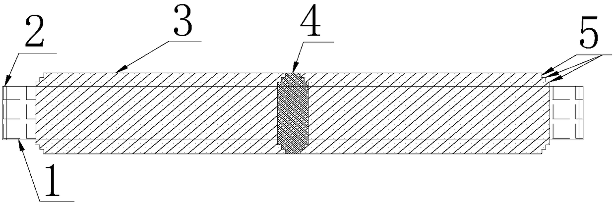
[0045] Such as figure 1 — figure 2 As shown, the present invention includes two parts: indoor pre-insulation and outdoor heat insulation. Among them, indoor pre-insulation is foamed with cyanate ester and polyether as the main raw materials, and is evenly sprayed on the pipeline by specific equipment to form a polyurethane insulation layer. 5, a heat insulation method, the heat insulation layer is a three-layer structure; the following construction steps are used for indoor pre-insulation:

[0046] The first step: install the shear key 4 in the middle of the pipeline 1 that has been sprayed; it is used as the innermost layer of the pipeline 1 for heat insulation; the specific steps for installing the shear key 4 are as follows:

[0047] 1. Scrape off the coating of the pipeline 1 at the installation position of the shear key 4. The scraped length should be slightly less than the total length of the shear key 4, and there should be 10mm of coating at each end below the shear ...


PUM


Abstract

A heat insulation construction process for a liquefied petroleum gas low-temperature conveying pipeline comprises indoor pre-heat-insulation and outdoor heat insulation. Indoor pre-heat-insulation construction comprises the steps that firstly, a shear key is arranged on the pipeline; secondly, elastic needle-like glass felts are arranged on the two sides of the shear key and fixed; thirdly, the elastic needle-like glass felts are wound by a first glass cloth layer and fixation is carried out; fourthly, a polyurethane foam heat insulation layer is sprayed; fifthly, a glass fiber reinforced plastic protective layer is sprayed and formed; sixthly, end portion sealing is carried out, and the spraying pre-heat-insulation work is completed; and seventhly, an end portion pipe cap is installed. Outdoor heat insulation construction comprises the steps that firstly, foam tiles are installed; secondly, a waterproof aluminum foil layer is arranged; thirdly, a tee joint, a bend, a support pipe base and a valve heat insulation part are installed; fourthly, heat insulation is carried out at the position of a welded junction on spot; fifthly, an outer protective layer is arranged; and seventhly, end portion protection is carried out. By means of the heat insulation construction process, all pipelines can be subjected to tight heat insulation, and the heat insulation effect is greatly improved; and moreover, the heat insulation construction process cannot be affected by the weather, and the heat insulation problem of the liquefied petroleum gas low-temperature conveying pipeline is solved.

Description

technical field [0001] The invention relates to a liquefied petroleum natural gas transmission pipeline, in particular to a thermal insulation construction process for a liquefied petroleum natural gas low-temperature transmission pipeline. Background technique [0002] The temperature range of existing liquefied petroleum natural gas (LNG) low-temperature transmission pipelines is generally in the range of -40°C to -196°C, and the heat insulation construction process mainly uses polyurethane foaming on site as heat preservation. [0003] Polyurethane foaming on site refers to a kind of foaming material with carbamate, which is made of two configured foaming materials, namely: white material and black material, which are mixed under high-speed stirring according to a certain ratio and then undergo a chemical reaction A polymer of segmental repeating structural units. According to the process: polyurethane foam can be divided into two methods: machine automatic foaming and m...

Claims


Application Information

Patent Timeline
Patent Type & Authority Patents(China)
IPC IPC(8): F16L59/02
CPCF16L59/028
Inventor 张宏彬谢永春杨海军韩雁凌唐健王修来徐超郭祥张永伟黄太安
Owner CHINA NAT OFFSHORE OIL CORP
Why Eureka
Try Eureka