Phase-change energy storage and heating device as well as energy storage and heating method

A phase change heat storage and phase change energy storage technology, applied in central heating, can solve the problems of decreased utilization rate of waste heat, low efficiency of waste heat recovery and utilization system, and high requirements for waste heat capacity

Active Publication Date: 2017-06-20
中益能(北京)供热技术有限公司 +1
View PDF10 Cites 10 Cited by
  • Summary
  • Abstract
  • Description
  • Claims
  • Application Information

AI Technical Summary

Problems solved by technology

[0006] 2) High waste heat grade requirements
Once the user determines the temperature of the water supply, strict requirements are placed on the fluctuation of waste heat supply. Therefore, the use of conventional waste heat recovery and utilization process technology solutions requires the fluctuation of waste heat to be small, because the waste heat recovery system does not have a heat storage device, which limits a large number of Recycling of fluctuating waste heat in line with heating requirements
[0007] 3) The waste heat capacity requirement is high. For a large number of users whose heat supply load is dynamically changing, the conventional waste heat recovery and utilization process technology scheme requires the waste heat capacity to meet the user's maximum heat load, because the waste heat recovery system has no heat storage device. The utilization rate of waste heat is reduced, and the efficiency of the whole waste heat recovery and utilization system is low.
The use of conventional technology solutions will inevitably lead to excessive heat supply capacity and high investment. However, the utilization rate of waste heat is very low, which is extremely unfavorable for the utilization of waste heat.

Method used


Image

  • Phase-change energy storage and heating device as well as energy storage and heating method
  • Phase-change energy storage and heating device as well as energy storage and heating method
  • Phase-change energy storage and heating device as well as energy storage and heating method

Examples


Embodiment approach

[0137] According to a first embodiment of the present invention, a variable energy storage device is provided;

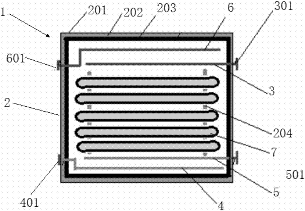
[0138] A phase change energy storage device 1, the device comprising:

[0139] 1) Energy storage device box body 2,

[0140] 2) Central heat storage component, which includes: heat supply outlet water distributor 3, heat storage return water distributor 4, heat supply return water distributor 5, heat storage outlet water distributor 6, phase change heat storage element 7 The heat supply and return water distributor 3 and the heat storage and return water distributor 4 are arranged on the upper part of the box body 2, and the heat supply and return water distributor 5 and the heat storage and outlet water distributor 6 are arranged on the lower part of the box body 2. The change heat storage element 7 is arranged in the middle of the box body 2, and a plurality of phase change heat storage elements 7 are arranged in an array or a laminated body,

[0141] Wherein, t...

Embodiment 1

[0219] Phase change heat storage materials include the following components:

[0220]

[0221]

[0222] Preparation process: heat and melt the component a), continue to heat up to 90°C, then add other components, stir and mix to form a phase-change heat storage material in the form of a mixture. The density (ρ) of the mixture is 2520kg / m 3 . Phase transition temperature range: 82-95°C. Latent heat of phase change (L) = 322-333kJ / kg. Specific heat capacity (Cp) = 5.52 kJ / kg·°C. The mixture was heated from 50°C to 90°C with a volume expansion rate of 0.05%.

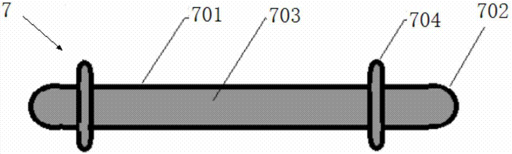
[0223] Filling: Let the mixture cool to about 40°C, fill it into the tube-shaped or rod-shaped heat storage element (7), and weld the sealed port.

Embodiment 2

[0229] A phase change energy storage device 1, the device comprising:

[0230] 1) Energy storage device box body 2,

[0231] 2) Central heat storage component, which includes: heat supply outlet water distributor 3, heat storage return water distributor 4, heat supply return water distributor 5, heat storage outlet water distributor 6, phase change heat storage element 7 The heat supply and return water distributor 3 and the heat storage and return water distributor 4 are arranged on the upper part of the box body 2, and the heat supply and return water distributor 5 and the heat storage and outlet water distributor 6 are arranged on the lower part of the box body 2. The change heat storage element 7 is arranged in the middle of the box body 2, and 20 phase change heat storage elements 7 are arranged in an array or a laminated body,

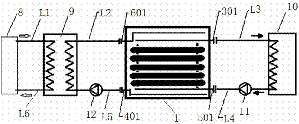
[0232] Wherein, the outlet 301 of the heat supply outlet water distributor 3 is located at the upper part of the outer side of the energy stora...


PUM


Abstract

A phase-change energy storage and heating device (1) comprises an energy storage equipment box body (2) and a central heat storage assembly, wherein the central heat storage assembly comprises a heating water-outlet water distributor (3), a heat-storage water-return water distributor (4), a heating water-return water distributor (5), a heat-storage water-outlet water distributor (6) and phase-change heat storage elements (7); the heating water-outlet water distributor (3) and the heat-storage water-return water distributor (4) are arranged at the upper part of the energy storage equipment box body (2); the heating water-return water distributor (5) and the heat-storage water-outlet water distributor (6) are arranged at the lower part of the energy storage equipment box body (2); and the phase-change heat storage elements (7) are arranged at the middle of the energy storage equipment box body (2), and distributed in an array or a laminate. The phase-change energy storage and heating device has the following functions: various phase-change heat storage materials can be converted into heat storage elements, and the heat storage elements can be distributed according to the unified arrangement mode and structure in different containers for heat storage and heating. Therefore, the heating energy consumption of the city life can be lowered, and the comprehensive recovery and utilization ratio of industrial waste heat can be improved.

Description

technical field [0001] The invention relates to a heat recovery, storage, and reuse device and method thereof, in particular to a phase change energy storage device and a heat storage and release method thereof, belonging to the energy-saving and environment-friendly field. Background technique [0002] my country's industrial energy utilization rate is generally low, with an average of less than 27%. For example, 65% of the high-quality waste heat generated in the production process of various industries such as municipal waste incineration, landfill gas, iron and steel, metallurgy, chemical industry, sewage treatment, and power generation The left and right are basically recovered for power generation and industrial steam, but the intermittent, unstable, and low-quality waste heat accounting for more than 85% of the total waste heat has not been fully recovered due to the lack of mature heat storage technology and engineering equipment. The recovery and utilization of waste ...

Claims


Application Information

Patent Timeline
Patent Type & Authority Applications(China)
IPC IPC(8): F24D3/02F24D3/10F24D11/00F28D20/00
CPCF24D3/02F24D3/10F24D11/002F28D20/00F28D20/0056Y02E60/14
Inventor 王智慧
Owner 中益能(北京)供热技术有限公司
Why Eureka
Try Eureka