
Method and laser radar system for measuring depth of water

A technology of optical system and receiving optical system, which is applied in the field of laser radar system solutions, can solve the problems of low measurement accuracy, high cost, and low efficiency, and achieve the effects of high measurement efficiency, low cost, and simple processing process

Inactive Publication Date: 2017-06-20
HARBIN INST OF TECH
View PDF4 Cites 12 Cited by
  • Summary
  • Abstract
  • Description
  • Claims
  • Application Information

AI Technical Summary

Problems solved by technology

[0003] The purpose of the present invention is to provide a method for measuring water depth and a laser radar system to solve the problems of high cost, low efficiency and low measurement accuracy in the prior art

Method used


Image

  • Method and laser radar system for measuring depth of water

Examples


specific Embodiment approach 1

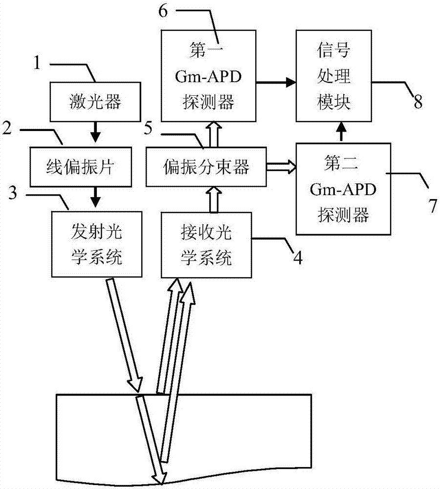
[0015] Specific implementation mode one: combine figure 1 Describe this embodiment, a kind of method of measuring water depth described in this embodiment is:

[0016] performing linear polarization modulation on the laser pulse signal emitted by the laser (1), so that the linear polarization modulated laser pulse signal is transmitted to the water surface in a nearly vertical direction through the transmitting optical system (3);

[0017] The water surface and bottom echo signals are received by the receiving optical system (4) and sent to the polarization beam splitter. The water surface echo signals are transmitted from the polarization beam splitter (5), and the bottom echo signals are reflected from the polarization beam splitter. A Gm-APD single photon detector respectively detects the arrival time of the two beams of light;

[0018] The water depth is calculated from the difference in arrival time of the two beams of light.

[0019] In this embodiment, linear polariza...

specific Embodiment approach 2

[0020] Specific implementation mode two: combination figure 1 Describe this embodiment, a laser radar system for measuring water depth described in this embodiment includes a laser (1), a linear polarizer (2), a transmitting optical system (3), a receiving optical system (4), and a polarizing beam splitter (5), the first Gm-APD single photon detector (6), the second Gm-APD single photon detector (7) and signal processing module (8);

[0021] After the laser light emitted by the laser (1) is transmitted through the linear polarizer (2), it is emitted to the water surface by the emission optical system (3);

[0022] The receiving optical system (4) is used to receive the water surface and underwater echo signals. The water surface and underwater echo signals emitted from the receiving optical system (4) are divided into two beams by the polarization beam splitter (5), and one beam is incident on the first Gm -APD single photon detector (6), another beam incident to the second G...


PUM


Abstract

The invention provides a method and a laser radar system for measuring the depth of water, and relates to the technical field of laser detection, aiming at solving the problems that the prior art is high in cost, low in efficiency and low in measurement accuracy. The method is characterized in that liner polarization modulation is carried out on a laser pulse signal sent by a laser, and the laser pulse signal subjected to the liner polarization modulation is vertically transmitted to the water surface by an optical transmitting system; an echo signal is received by using an optical receiving system and is divided into two beams by using a polarization beam splitter; two Geiger mode-avalanche photodiode (Gm-APD) single-photon detectors are respectively used for detecting the arrival time of the two beams of light; a signal processing module calculates the depth of water according to the difference of the arrival time of the two beams of light. The method is low in cost of used optical devices, simple and easy in measurement process, simple in signal processing process and high in measurement efficiency. The Gm-APD single-photon detectors can effectively improve the measuring sensitivity and even also can be used for measuring a single-photon echo signal in a deeper water area, so that the application scopes of the method and the system which are provided by the invention are expanded.

Description

technical field [0001] The invention relates to the technical field of laser detection, in particular to a laser radar system scheme for realizing water depth measurement by utilizing the polarization characteristics of echo signals. Background technique [0002] Water depth measurement is the main means for people to obtain seabed or river topographic data, and is an important means for obtaining underwater topographic data surveying and mapping. The underwater terrain often changes due to the flow of the water body, which poses a great safety hazard to the navigation of the ship. Therefore, researchers have conducted in-depth research on how to obtain the water depth. Traditional methods of obtaining water depth include shipborne sonar detection, airborne laser detection, submersible detection, hyperspectral image measurement, etc. However, they generally have the characteristics of high cost and low efficiency, and the measurement accuracy of some methods is also affecte...

Claims


Application Information

Patent Timeline
Patent Type & Authority Applications(China)
IPC IPC(8): G01F23/284
CPCG01F23/284
Inventor 张子静赵远岑龙柱张建东李硕
Owner HARBIN INST OF TECH
Learn More