Ceramic kiln with cooling control structure

A ceramic kiln and control structure technology, applied in the field of ceramic kiln, can solve the problems of increasing temperature field uniformity, uncontrollable temperature and atmosphere, unevenness, etc., to achieve uniform temperature field, reduce temperature difference, and strong automatic adjustment ability Effect

Inactive Publication Date: 2017-06-23
杭州志在材料科技有限公司 +1
View PDF10 Cites 2 Cited by
  • Summary
  • Abstract
  • Description
  • Claims
  • Application Information

AI Technical Summary

Problems solved by technology

[0004] The purpose of the present invention is to propose a ceramic kiln with a cooling control structure. Aiming at the problem of uncontrollable and uneven temperature and atmosphere during cooling in the ceramic firing process, the structure of the existing ceramic kiln is improved. Thermal radiation and gas convection, so as to ensure that the temperature in the furnace can meet the preset cooling process, and effectively increase the uniformity of the temperature field during the cooling process on the premise of improving the ceramic firing efficiency

Method used


Image

  • Ceramic kiln with cooling control structure
  • Ceramic kiln with cooling control structure
  • Ceramic kiln with cooling control structure

Examples


Embodiment Construction

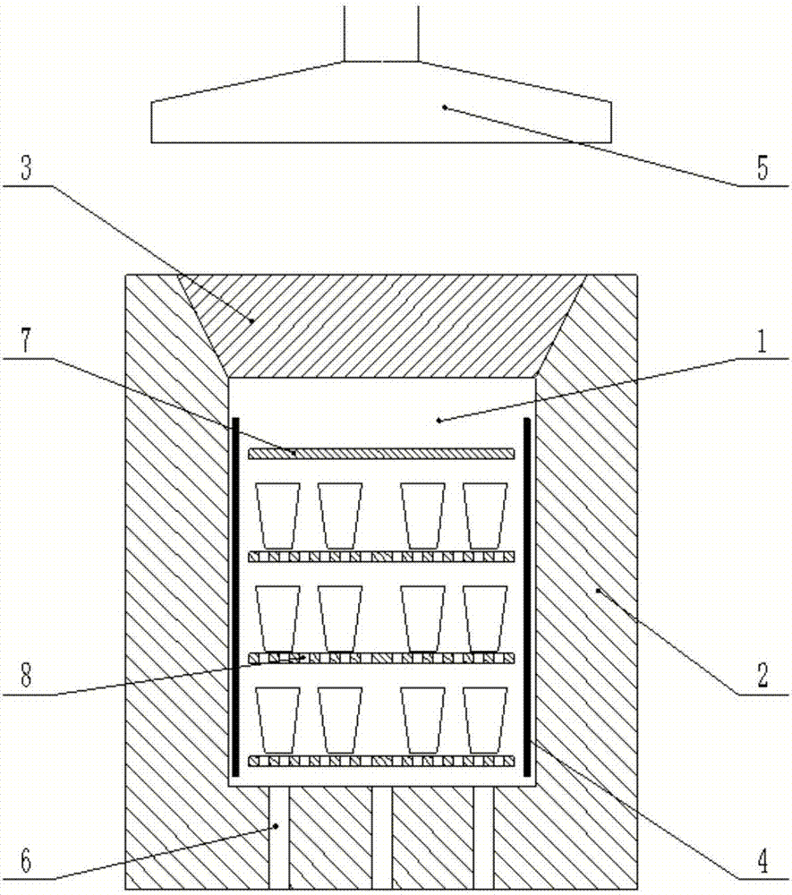
[0018] The ceramic kiln with cooling control structure proposed by the present invention has a structure such as figure 1 As shown, it includes a furnace 1, an outer wall of a kiln 2, a liftable top cover 3, a heater 4, a smoke collection and exhaust hood 5, a controlled air intake pipe 6, a soaking shed 7 and a perforated ventilation shed 8. The heater 4 is arranged on the four walls of the furnace 1, and the perforated ventilation sheds 8 are longitudinally arranged in the furnace 1, and the body to be fired is placed on the perforated and ventilated shelvings 8 . The soaking shed plate 7 is positioned above the uppermost green body to be fired. The lower part of the furnace 1 is provided with a controlled air intake pipe 6 , the upper part of the furnace 1 is provided with a liftable top cover 3 , and a smoke collection and exhaust hood 5 is provided above the liftable top cover 3 .

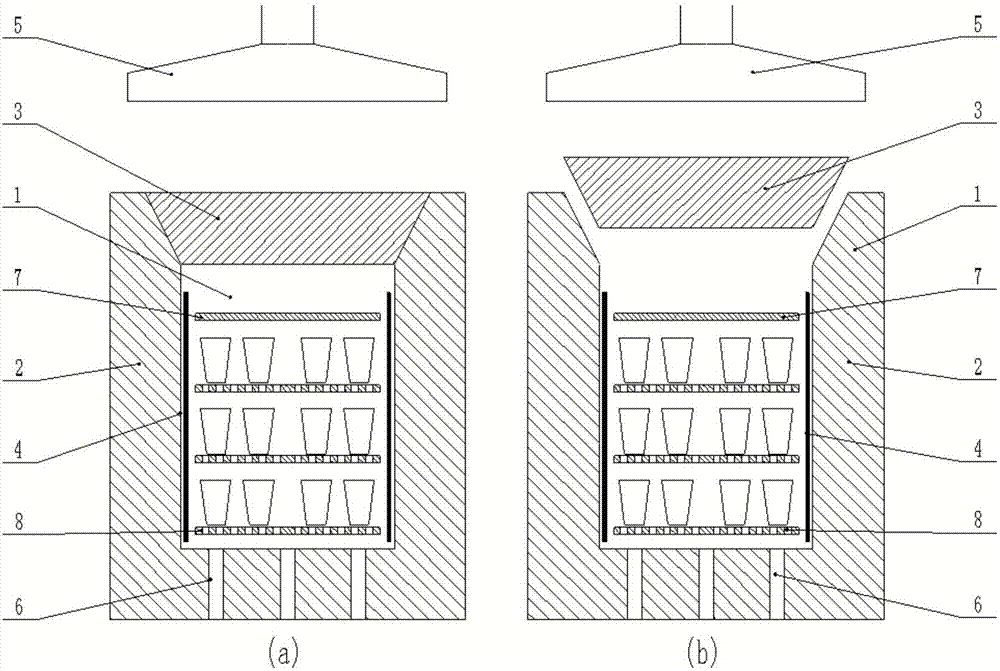
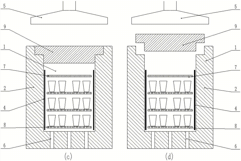
[0019] In the above-mentioned ceramic kiln with cooling control structure, the liftable t...


PUM


Abstract

The invention relates to a ceramic kiln with a cooling control structure, and belongs to the technical field of ceramic firing. The ceramic kiln comprises a hearth, a hearth outer wall, a liftable top cap, heaters, a smoke exhaust hood, a controlled air inlet pipeline, a soaking refractory slab and perforated ventilating refractory slabs, wherein the heaters are arranged on the walls of the hearth, and the perforated ventilating refractory slabs are arranged in the hearth longitudinally; a green body to be fired is arranged on the perforated ventilating refractory slabs, and the soaking refractory slab is located above the green body to be fired; the lower part of the hearth is provided with the controlled air inlet pipeline, and the upper part of the hearth is provided with the liftable top cap; the smoke exhaust hood is arranged above the top cap. The temperature in the ceramic kiln provided by the invention is controlled and reduced through controlling radiation quantity and natural convection quantity, and the liftable top cap is controlled; air enters from the bottom, and smoke is collected and exhausted from the top; a temperature field of a ceramic firing cooling stage and atmosphere uniformity are ensured. The ceramic kiln provided by the invention has the advantages of strong practicability and broad application prospect, and the ceramic production efficiency and the rate of finished products can be improved effectively.

Description

technical field [0001] The invention relates to a ceramic kiln with a cooling control structure, which belongs to the technical field of ceramic firing. Background technique [0002] At present, people have realized that the process that has a great influence on the firing quality in the firing process of craft ceramics is the mutual matching relationship between the temperature in the heating process of the kiln and the atmosphere of the kiln. After long-term practice and accumulation, people have also mastered rich experience in how to control the temperature and atmosphere in the kiln during the heating process of ceramic firing, but the research on the cooling process is not as deep as the heating process. In the traditional concept, the temperature and atmosphere during the cooling process do not affect the quality of porcelain, but in fact, with the development of modern technology, researchers have gradually realized that the uniformity of the atmosphere and temperatu...

Claims


Application Information

Patent Timeline
Patent Type & Authority Applications(China)
IPC IPC(8): F27B17/00F27D1/18F27D17/00
CPCF27B17/005F27B17/0075F27D1/1808F27D17/001F27D2001/1825F27M2001/035F27M2003/04
Inventor 王琤张松赵波张辉杨锐
Owner 杭州志在材料科技有限公司
Why Eureka
Try Eureka