
Remote integrated control system for industrial 4.0 coal-fired flue gas pollution control facility

A coal-fired flue gas and pollution control technology, which is applied in the direction of electrical program control, general control system, control/regulation system, etc., can solve the problems of not being able to analyze potential problems in time, increasing operating costs, and not being able to check the operation status of each project in real time. , to achieve the effect of saving personnel expenses, reducing operating costs and reducing staffing

Active Publication Date: 2017-06-23
SHANDONG GUOSHUN CONSTR GRP
View PDF5 Cites 2 Cited by
  • Summary
  • Abstract
  • Description
  • Claims
  • Application Information

AI Technical Summary

Problems solved by technology

[0003] The purpose of the present invention is to provide a remote comprehensive control system for industrial 4.0 coal-fired flue gas pollution control facilities, which is used to solve the problem that the existing DCS and video monitoring systems only operate independently, and large-scale professional operation teams cannot view them in real time within the same time period The operation of various projects distributed across the country cannot analyze potential problems in the operation process in a timely manner. When multiple sets of DCS systems are scattered in one site, the independent operation of the system will bring more staffing to the operation team. The problem of greatly increasing operating costs

Method used


Image

  • Remote integrated control system for industrial 4.0 coal-fired flue gas pollution control facility
  • Remote integrated control system for industrial 4.0 coal-fired flue gas pollution control facility
  • Remote integrated control system for industrial 4.0 coal-fired flue gas pollution control facility

Examples


Embodiment Construction

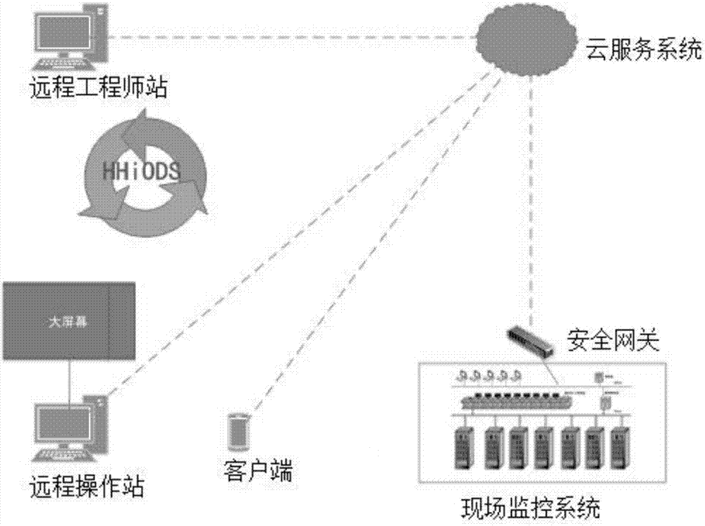
[0036] Such as figure 1 As shown, the remote integrated control system of industrial 4.0 coal-fired flue gas pollution control facilities, including

[0037] Remote engineer station for completing system database, history library, graphics, control language configuration and downloading functions; and,

[0038] A remote operation station for calling and displaying configuration graphics, displaying real-time data and status on site, displaying historical data, and completing control adjustment, trend display, and alarm display functions; and,

[0039] A client for invoking and displaying configured graphics, displaying on-site real-time data, device status, trend display, and alarm display functions; and,

[0040] A cloud service system for fulfilling client data requests and real-time data push tasks; and,

[0041] An on-site monitoring system for monitoring various types of equipment on site; and,

[0042]It is used to realize the communication with various fieldbus instr...


PUM


Abstract

The invention discloses a remote integrated control system for an industrial 4.0 coal-fired flue gas pollution control facility. The remote integrated control system comprises a remote engineer station, a remote operation station, a client, a cloud service system, a field monitoring system and a security gateway, wherein the remote engineer station is used for completing system database, history database, graphics and control language configuration and downloading functions; the remote operation station is used for calling and displaying configured graphics, displaying field real-time data and states and historical data and completing control regulation, trend display and alarm display functions; the client is used for calling and displaying the graphics, displaying the field real-time data and equipment states, and realizing the trend display and alarm display functions; the cloud service system is used for fulfilling client data request and real-time data pushing tasks; the field monitoring system is used for monitoring various field equipment; the security gateway is used for realizing communication with various types of field bus instruments, PLCs, intelligent equipment and RTUs, completing interpretation and data format conversion functions of various communication protocols and recording the historical data.

Description

technical field [0001] The invention relates to the technical field of environmental protection desulfurization DCS remote and video remote comprehensive control, in particular to an industrial 4.0 remote comprehensive control system for coal-fired flue gas pollution treatment facilities. Background technique [0002] At present, the traditional DCS control system is the product of a high degree of integration of computer technology, control technology and network technology. Usually, several controllers (process stations) are used to control many control points in a production process, and the controllers are connected through the network. And can carry out data exchange. The operation adopts a computer operation station, which is connected to the controller through the network, collects production data, and conveys operation instructions. Therefore, the main features of DCS can be summed up in one sentence: decentralized control and centralized management. The video surv...

Claims


Application Information

Patent Timeline
Patent Type & Authority Applications(China)
IPC IPC(8): G05B19/418
CPCG05B19/4186G05B2219/33273
Inventor 张丕军王青毕庚尧尹磊武云荣高超卢忠阳
Owner SHANDONG GUOSHUN CONSTR GRP
Learn More