K-wave-band high-efficiency continuous wave space travelling wave tube
A high-efficiency, traveling-wave tube technology, applied in the field of traveling-wave tubes, can solve the problems of low output efficiency, unreasonable design, poor heat dissipation, etc., and achieve the effects of high overall efficiency, reasonable structural design, and improved electrical performance.
Active Publication Date: 2017-06-23
NANJING SANLE GROUP
View PDF2 Cites 11 Cited by
- Summary
- Abstract
- Description
- Claims
- Application Information
AI Technical Summary
Problems solved by technology
[0003] However, the existing K-band high-efficiency continuous wave space traveling wave tube has unreasonable structural design, low output efficiency, short life, poor reliability and poor heat dissipation.
Method used
View moreImage
Smart ImageViewing Examples
Examples
Embodiment 2
[0048]The measured indicators of the K-band high-efficiency continuous wave space traveling wave tube provided by the present invention are as follows:
Login to View More PUM
 Abstract
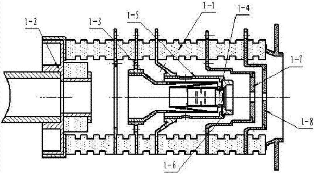
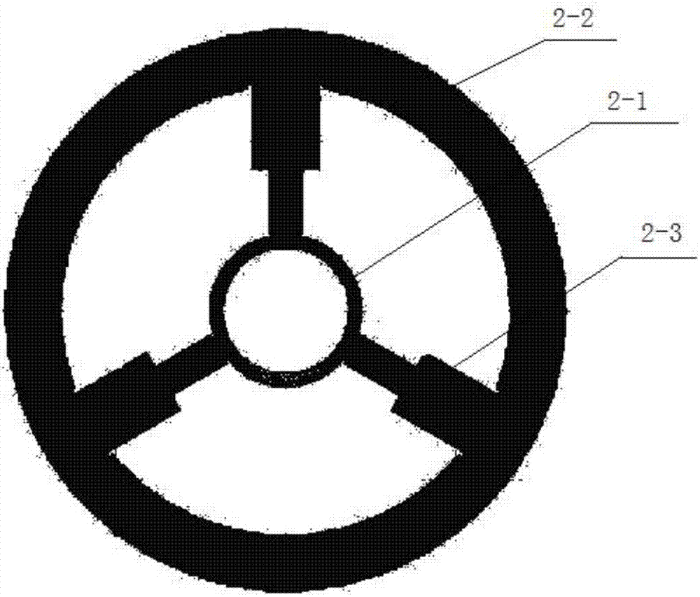
The invention discloses a K-wave-band high-efficiency continuous wave space travelling wave tube. The travelling wave tube comprises a double anode electron gun (1), a slow-wave circuit (2), a periodic permanent magnetic focusing system (6) and a level-four voltage reduction collector (3), wherein the slow-wave circuit (2) is connected to the double anode electron gun (1); the periodic permanent magnetic focusing system (6) is installed on a periphery of the slow-wave circuit (2); and the level-four voltage reduction collector (3) is connected to the slow-wave circuit (2). Two ends of the slow-wave circuit (2) are connected to an input waveguide (4) and an output waveguide (5). By using the K-wave-band high-efficiency continuous wave space travelling wave tube, the structure is designed reasonably, electronic efficiency is high, collector efficiency and total efficiency are high too, and performance is stable.
Description
technical field [0001] The invention relates to a traveling wave tube, in particular to a K-band high-efficiency continuous wave space traveling wave tube with high output efficiency, long service life, good reliability and good nonlinear index. Background technique [0002] The traveling wave tube is a microwave electron tube that realizes the amplification function by modulating the speed of the electron injection. The traveling wave tube is characterized by wide frequency band, high gain, large dynamic range and low noise. Difference / center frequency) can reach more than 100%, the gain is in the range of 25-70 decibels, and the noise figure of the low-noise traveling wave tube can reach as low as 1-2 decibels. Therefore, modern traveling wave tubes have become military radars, military electronic countermeasures, Important microwave electronic devices for relay communication, satellite communication, live TV satellite, navigation, remote sensing, remote control, telemetry...
Claims
Login to View More Application Information
Patent Timeline
 Patent Type & Authority Applications(China)
IPC IPC(8): H01J23/06H01J23/27H01J25/34
CPCH01J23/06H01J23/27H01J25/34H01J2223/06H01J2223/27H01J2225/34
Inventor 高志强陈昀董笑瑜刘强宋泽淳胥辉黄鹏潮綦伟玲田航周培章
Owner NANJING SANLE GROUP
Features
- R&D
- Intellectual Property
- Life Sciences
- Materials
- Tech Scout
- Unparalleled Data Quality
- Higher Quality Content
- 60% Fewer Hallucinations
Learn More Browse by: Latest US Patents, China's latest patents, Technical Efficacy Thesaurus, Application Domain, Technology Topic, Popular Technical Reports.
© 2025 PatSnap. All rights reserved.Legal|Privacy policy|Modern Slavery Act Transparency Statement|Sitemap|About US| Contact US: help@patsnap.com


