Vibration reduction and isolation system for high-speed centrifugal extractor

A centrifugal extractor, vibration and vibration isolation technology, applied in liquid solution solvent extraction, mechanical equipment, spring/shock absorber, etc., can solve the problems of dynamic imbalance, fatigue damage, cumulative error of rotating parts of centrifugal extractor, etc. Achieve the effect of reducing vibration, widening the structure type, and improving the separation effect

Pending Publication Date: 2017-06-27
HEFEI GENERAL MACHINERY RES INST
View PDF11 Cites 3 Cited by
  • Summary
  • Abstract
  • Description
  • Claims
  • Application Information

AI Technical Summary

Problems solved by technology

The reasons for the vibration are: 1. The impact of the material entering the centrifugal extractor; 2. The material may contain solids or colloids, and may also produce precipitates during the extraction process, causing solids in the centrifugal extractor to adhere to the inner wall of the drum. 3. During the lifting speed of the centrifugal extractor, it is similar to the natural frequency of the centrifugal extractor, resulting in resonance; 4. The cumulative error of the rotating parts of the centrifugal extractor during processing and assembly, etc.
Vibration will bring the following problems: 1. Affect the safety and use of the centrifugal extractor; 2. Affect the separation and extraction effect of the centrifugal extractor; 3. Long-term vibration will cause fatigue damage; 4. Affect the foundation of the centrifugal extractor, especially When the centrifugal extractor is placed on a steel frame platform

Method used


Image

  • Vibration reduction and isolation system for high-speed centrifugal extractor
  • Vibration reduction and isolation system for high-speed centrifugal extractor
  • Vibration reduction and isolation system for high-speed centrifugal extractor

Examples


Embodiment

[0028] Embodiment: Referring to the accompanying drawings, the vibration reduction and vibration isolation system of the high-speed centrifugal extractor of this embodiment:

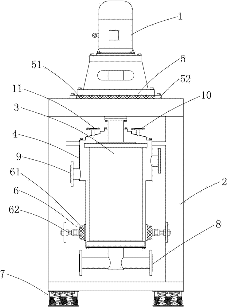
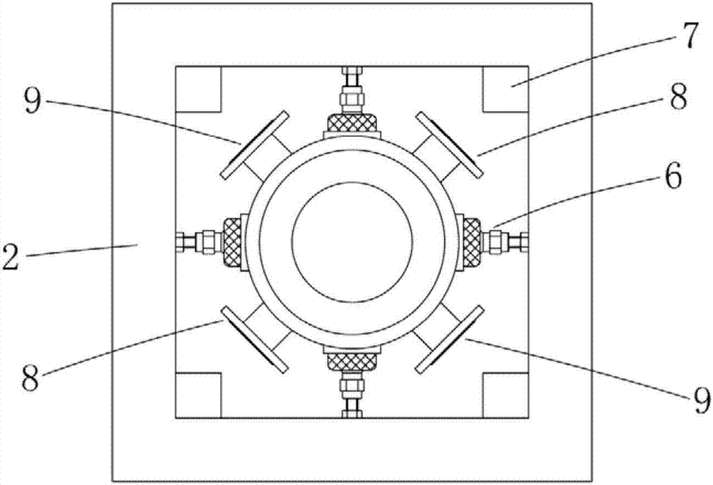
[0029] It includes a transmission part 1, a frame 2, a rotating part 3, and an outer casing 4 of the rotating part. The transmission part 1 provides rotational power for the rotating part 3. The transmission part 1 is arranged on the top of the frame, and is generally composed of a motor, a coupling etc., the motor provides rotating power, and the coupling connects the motor and the rotating part 3.

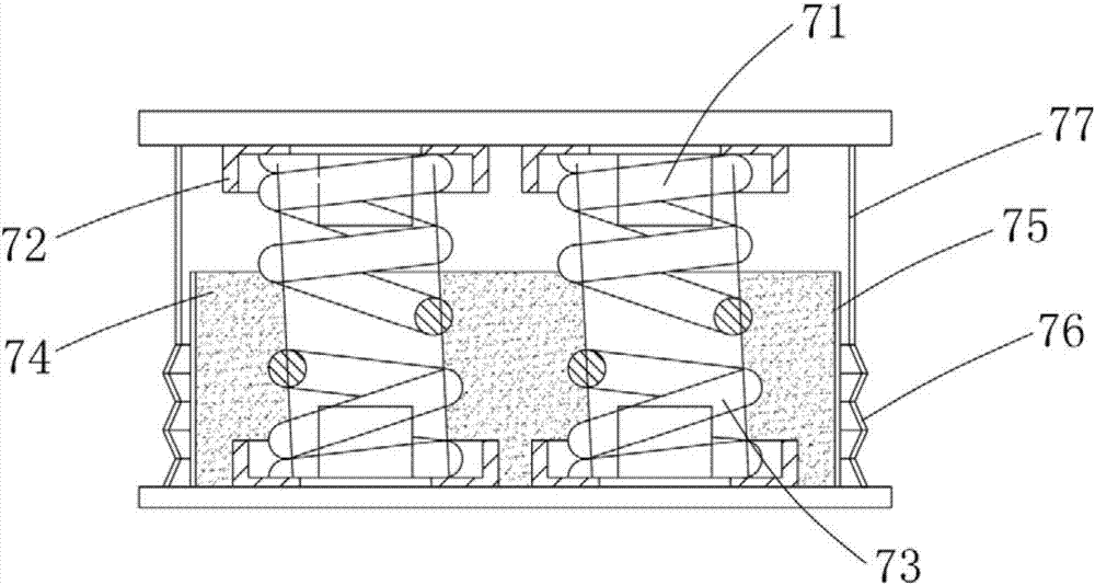
[0030] figure 1 As shown, the rotating part 3 is suspended inside the frame 2, and an elastic shock absorber 5 is arranged on the top of the frame 2, and the upper part of the rotating part 3 is supported on the frame 2 by the elastic shock absorber 5;

[0031] During processing, the frame 2 supports the transmission part 1, the rotating part 3 and the outer casing (4) of the centrifugal extractor, and is ...


PUM


Abstract

The invention discloses a vibration reduction and isolation system for a high-speed centrifugal extractor. The centrifugal extractor comprises a transmission part, a rack, a rotating part and an outer shell of the rotating part, the transmission part provides rotating power for the rotating part, and the transmission part is arranged on the top of the rack; the rotating part is arranged inside the rack in a suspending manner, an elastic vibration absorption body is arranged on the top of the rack, and the upper portion of the rotating part is supported to the rack through the elastic vibration absorption body; and multiple disc-type vibration isolators are evenly distributed on the outer wall of the outer shell of the rotating part in the peripheral direction, and the disc-type vibration isolators are attached to the outer wall of the outer shell through telescoping mechanisms arranged on the rack leg columns. According to the vibration reduction and isolation system for the high-speed centrifugal extractor, the vibration reduction and isolation system is additionally installed on the centrifugal extractor, and by means of positively eliminating dynamic unbalance of the rotating part, eliminating flutter of an outer shell of a thin-walled part, isolating vibration between equipment and a foundation and the like, vibration of the centrifugal extractor is greatly reduced.

Description

[0001] Technical field: [0002] The invention relates to a vibration reduction and isolation system for a high-speed centrifugal extractor. [0003] Background technique: [0004] The operation of extracting a certain component from a liquid mixture with a solvent is called liquid / liquid extraction. [0005] Centrifugal extractor is a fast and efficient liquid / liquid extraction (solvent extraction) equipment, which uses centrifugal force to realize the extraction and separation of liquid-liquid two-phase. The rotational speed of the centrifugal extractor is an important technical parameter, which determines the size of its separation factor and thus determines the quality of the extraction and separation effect. In terms of technological development and practical application, centrifugal extractors are developing towards high speed. But the vibration problem of high-speed centrifugal extractor restricts its development and application. The reasons for the vibration are: 1. ...

Claims


Application Information

Patent Timeline
Patent Type & Authority Applications(China)
IPC IPC(8): F16F15/02F16F15/023F16F15/04B01D11/04
CPCB01D11/04F16F15/022F16F15/023F16F15/046
Inventor 陈崔龙张德友方毅陈道林
Owner HEFEI GENERAL MACHINERY RES INST
Why Eureka
Try Eureka