Eureka AIR delivers breakthrough ideas for toughest innovation challenges, trusted by R&D personnel around the world.

Finned tube heat exchanger and application thereof and afterheat boiler

A finned tube heat exchanger and fin technology, which is applied in the field of finned tube heat exchangers and waste heat boilers, to achieve the effect of weakening the unfavorable factors of heat transfer, strengthening the radial heat transfer capacity, and improving the heat transfer efficiency

Active Publication Date: 2017-06-27
HUNAN UNIV OF TECH
View PDF6 Cites 4 Cited by
  • Summary
  • Abstract
  • Description
  • Claims
  • Application Information

AI Technical Summary

Problems solved by technology

[0005] The technical problem to be solved by the present invention is to aim at the deficiencies of the existing technology, and according to the field synergy theory, provide a kind of high heat transfer efficiency, short axial length and small volume Finned tube heat exchanger

Method used


Image

  • Finned tube heat exchanger and application thereof and afterheat boiler
  • Finned tube heat exchanger and application thereof and afterheat boiler
  • Finned tube heat exchanger and application thereof and afterheat boiler

Examples


Embodiment 1

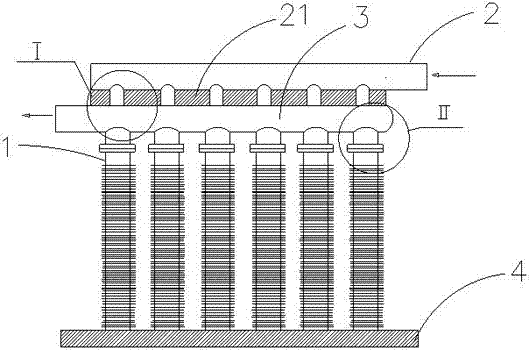
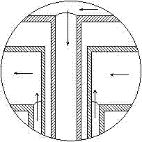
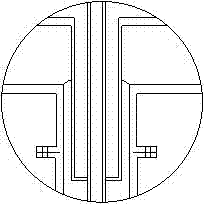
[0043] Such as Figure 1~4 As shown, this embodiment provides a finned tube heat exchanger, including a water inlet pipe 2, an outlet pipe 3 and a heat pipe 1 connecting the water inlet pipe 2 and the water outlet pipe 3, and the heat pipe 1 is also provided with a tube plate 4 for fixing the heat pipe 1 , the heat pipe 1 is connected with the water inlet pipe 2 and the water outlet pipe 3 in parallel;

[0044] The heat pipe 1 includes a first layer inner tube 12, a second layer inner tube 11 and an outer tube 13 of different diameters, the first layer inner tube 12 and the second layer inner tube 11 form a double-layer inner tube, and the first layer inner tube 12 sets There is a second layer of inner tube 11; the outer tube 13 is covered with a double-layer inner tube; the first layer of inner tube 12 communicates with the second layer of inner tube 11; the first layer of inner tube 12 and the outer tube 13 are closed structures and constitute Annular channel heat pipe 17, ...

Embodiment 2

[0051] Such as Figure 5 As shown, this embodiment is basically the same as Embodiment 1, except that the heat pipe 1 is connected to the water inlet pipe 2 and the water outlet pipe 3 in series.

Embodiment 3

[0053] Such as Image 6 As shown, this embodiment provides a waste heat boiler provided with the finned tube heat exchanger, including a finned tube heat exchanger, a drum 106 and a flue 104 outside the drum, and the finned tube heat exchanger It is arranged in the flue 104 , the water inlet pipe 102 is connected to the cold water interface 105 , the water outlet pipe 103 is connected to the drum 106 , and the heat pipe 101 is perpendicular to the flue 104 .

[0054] This embodiment is an application of the finned tube heat exchanger in industrial waste heat. The finned tube heat exchanger of the present invention does not need a casing, has a small volume, and can be arranged in the flue 104 very flexibly, and the heat pipe 101 and the flue gas The channel 104 makes full use of the feature of radial heat transfer vertically to achieve the largest heat exchange area. At the same time, the water inlet pipe 102 is connected to the cold water interface 105, and the cold water is ...


PUM


Abstract

The invention relates to the technical field of heat exchangers, and discloses a finned tube heat exchanger and application thereof and an afterheat boiler. The finned tube heat exchanger belongs to a radial heat transfer heat tube, and has the advantages of high heat transfer efficiency, short axial length, small size and light unit heat exchange weight; a sucking core has no need to be arranged in the tube; and inner tube fins of a first layer of inner tubes can be used for guiding condensed water to flow onto the inner walls of outer tubes to absorb heat for evaporation, so that the whole inner walls of the outer tubes become the heat absorption evaporation surface area of phase change liquid. The finned tube heat exchanger is applied to industrial afterheat, can reduce industrial pollution, and also can fully use the industrial afterheat; and the industrial afterheat is secondarily converted to energy for recycling by human. The afterheat boiler adopts the finned tube heat exchanger consisting of heat tubes to recover heat; the finned tube heat exchanger is small in size, and can be flexibly arranged on a flue; and the heat tubes belong to radial heat transfer, so that the heat exchange area with waste smoke in the flue is largely increased, and the heat exchange efficiency is improved.

Description

technical field [0001] The invention relates to the technical field of heat exchangers, in particular to a finned tube heat exchanger, its application and a waste heat boiler. Background technique [0002] Mineral energy is becoming increasingly scarce today, and the human living environment is also severely damaged, especially the emission of greenhouse gases. The problems of the human living environment are becoming more and more prominent. It is an indisputable fact that island countries threaten the safety of coastal cities. The increasingly serious smog problem in our country has not been solved for a long time, which has seriously affected people's health and increased the chances of people suffering from lung cancer. The serious smog phenomenon is difficult to fundamentally solve. The exhaust gas is increasing day by day, but the spontaneous factors in nature itself are rare. We also know that more than 80% of the energy used by human beings needs to go through the ...

Claims


Application Information

Patent Timeline
Patent Type & Authority Applications(China)
IPC IPC(8): F28D15/02F22B1/18F22B31/08
CPCF22B1/18F22B31/08F28D15/0266Y02E20/30
Inventor 向立平王汉青寇广孝李灿欧阳琴邬志伟
Owner HUNAN UNIV OF TECH
Why Eureka
Eureka Blog
Learn More